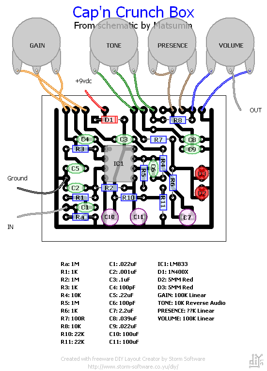
MI Audio - Crunch Box  [traced]

General documentation, gut shot, schematic links, ongoing circuit tracing, deep thoughts ... all about boutique stompboxes.
User avatar
lynessmy
Breadboard Brother
Information
Posts: 112
Joined: 09 Oct 2007, 01:15
Has thanked: 1 time
Been thanked: 2 times

Post by lynessmy »

audioguy wrote:
lynessmy wrote:I have a layout too in my blog...
I built one from your layout today and it didnt work. I'll do some testing on it tomorrow... but its dead silent.

I'll post some info tomorrow.
My build had no problem. :scratch: Don't forget those jumper wire, there are 2 there..... :hmmm: just in case you didn't notice.
I'm doing REV2 now.
Hopefully it fire up at the first shot.
Then this is the one i will give him a house (enclosure).

User avatar
audioguy
Resistor Ronker
Information
Posts: 262
Joined: 27 Nov 2007, 14:47
Has thanked: 22 times
Been thanked: 7 times

Post by audioguy »

Yeah the jumpers were the first thing I looked at to make sure I found them all... they look good. I dont know if I'll have time to trouble shoot it today. I might wait till you do Rev2- this is a small build. It would probably take less time to rebuild then it would to troubleshoot the one I've got done already. Its probably something simple- I'm not even getting the on board LEDs to light up.

thanks for the cool layouts!!

User avatar
lynessmy
Breadboard Brother
Information
Posts: 112
Joined: 09 Oct 2007, 01:15
Has thanked: 1 time
Been thanked: 2 times

Post by lynessmy »

audioguy wrote:Yeah the jumpers were the first thing I looked at to make sure I found them all... they look good. I dont know if I'll have time to trouble shoot it today. I might wait till you do Rev2- this is a small build. It would probably take less time to rebuild then it would to troubleshoot the one I've got done already. Its probably something simple- I'm not even getting the on board LEDs to light up.

thanks for the cool layouts!!
Version 2 is up at my blog....

User avatar
Valoosj
Breadboard Brother
Information
Posts: 51
Joined: 28 Mar 2008, 14:03
Location: Antwerp, Belgium
Been thanked: 1 time

Post by Valoosj »

Deric wrote:Thanks guys. Here is the updated layout with the Presence wiring corrected.........

Image


hmmmm...not sure why but the thumbnail still shows the wrong layout. If you click on it though the link shows the correct one..... :?
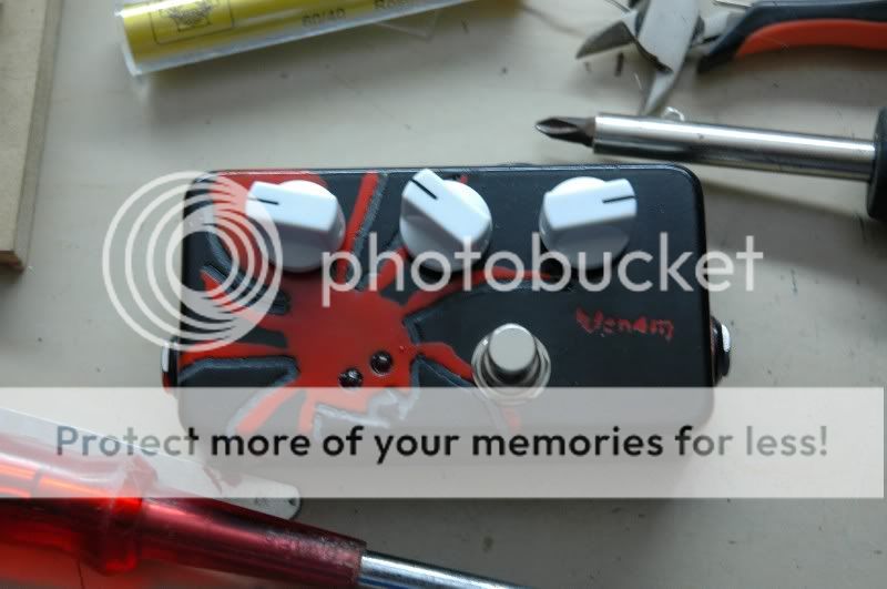
I built this pedal according to the above layout. The only difference is that I used normal film instead of the Tantalums. Does this matter?? I can replace thim if you think so. The presence knob is a trimmer in my version. Haven't played around with it. Might do that soon.

Here are some pics.
Image
Image
Image
Bazinga!

User avatar
soulsonic
Old Solderhand
Information
Posts: 3880
Joined: 27 Jun 2007, 03:38
my favorite amplifier: Traynor YVM-1
Completed builds: too many!
Location: Morgantown, WV
Has thanked: 183 times
Been thanked: 468 times
Contact:

Post by soulsonic »

Cool glow effect with the spider!

I think film caps may even sound better than Tantalum.
"Analog electronics in music is dead. Analog effects pedal design is a dead art." - Fran

User avatar
Valoosj
Breadboard Brother
Information
Posts: 51
Joined: 28 Mar 2008, 14:03
Location: Antwerp, Belgium
Been thanked: 1 time

Post by Valoosj »

soulsonic wrote:Cool glow effect with the spider!

I think film caps may even sound better than Tantalum.
Ok. And thanks :) One of my best finished pedals so far.
Bazinga!

User avatar
underage
Information
Posts: 19
Joined: 01 Jun 2008, 14:44

Post by underage »

paperhouse wrote:here's my build:

Image

i mounted the clipping LED's externally as the eyes and they light up with your pick attack:

Image

sounds awesome with the gain cranked but it's a little dull when the gain is lowered. it prefers humbuckers, but i think that's the nature of marshally pedals. cool pedal and recommended build.
Wehick layout u used ?? thanks

User avatar
underage
Information
Posts: 19
Joined: 01 Jun 2008, 14:44

Post by underage »

audioguy wrote:Yeah the jumpers were the first thing I looked at to make sure I found them all... they look good. I dont know if I'll have time to trouble shoot it today. I might wait till you do Rev2- this is a small build. It would probably take less time to rebuild then it would to troubleshoot the one I've got done already. Its probably something simple- I'm not even getting the on board LEDs to light up.

thanks for the cool layouts!!
what is the difference between version 1 and 2 ? thanks

User avatar
JeawJaw
Information
Posts: 8
Joined: 08 Nov 2007, 18:50

Post by JeawJaw »

Here my build..

it is Crunch box clone(PCB and Schematic) . but sound between original and clone was little different.
I like it.
Attachments
P1010160.jpg
P1010160.jpg (25.22 KiB) Viewed 2492 times
Clone Crunch box
Clone Crunch box

User avatar
JeawJaw
Information
Posts: 8
Joined: 08 Nov 2007, 18:50

Post by JeawJaw »

two yellow capcitor in red square. What 's type capacitor ?

I guess it may be tantalum, or ceramic multilayer.

anyone have information or more gut , please.....
Attachments
P2190015.jpg

User avatar
Torchy
Information

Post by Torchy »

From the photo, theyre dipped ceramic multilayer.

User avatar
JeawJaw
Information
Posts: 8
Joined: 08 Nov 2007, 18:50

Post by JeawJaw »

More gut..

thank you Torchy
Attachments
crunch_box.jpg

User avatar
johanwastaken
Information
Posts: 12
Joined: 26 Mar 2008, 22:50

Post by johanwastaken »

In the schematic, there is something called "V1 006P". What kind of part is that?

User avatar
nooneknows
Resistor Ronker
Information
Posts: 341
Joined: 26 Mar 2008, 21:53
Has thanked: 58 times
Been thanked: 15 times

Post by nooneknows »

Hi,
I've built the pedal, 1st version posted without the presence: very muddy, much more than I expected, even if I read the posts before.
is the version with the pres pot clearer? anybody tried both schems?

I believe that double final filter could be one of the usual suspect, I was thinking about getting rid of R7, R8, R9, VR2, C8 and C9, and put instead a Mark Hammer SW ton control, with a 22k pot, a 10nF cap and a 1K8 res. I'll try it as soon as possible.

The crunch box is very close to the Guv'nor pedal (except the tone control), I've calculated the same frequency cuts. In the original Guv'nor schem there's a 22k and 470 pF going to ground after the volume, the crunch box hasn't... why? it seems a low pass filter (with a ft around 15KHz, I believe), maybe to make the pedal less shrill?

User avatar
new_pedal
Information
Posts: 1
Joined: 14 Oct 2007, 15:57

Post by new_pedal »

johanwastaken wrote:In the schematic, there is something called "V1 006P". What kind of part is that?
it is 9V battery.

User avatar
nooneknows
Resistor Ronker
Information
Posts: 341
Joined: 26 Mar 2008, 21:53
Has thanked: 58 times
Been thanked: 15 times

Post by nooneknows »

nooneknows wrote:I've built the pedal, 1st version posted without the presence: very muddy, much more than I expected, even if I read the posts before.
is the version with the pres pot clearer? anybody tried both schems?

I believe that double final filter could be one of the usual suspect, I was thinking about getting rid of R7, R8, R9, VR2, C8 and C9, and put instead a Mark Hammer SW ton control, with a 22k pot, a 10nF cap and a 1K8 res. I'll try it as soon as possible.
IT WORKS!!! it suddendly became one of the best overdrive I've ever heard and built!

referring to the Matsumin schematics:
- 1uF film in place of the 2.2 uF electro C7
- 1K8 R in place of the 100R R7
- a B25K (tone) pot in place of VR2 and R8 (one external lug to R7, the other external directly to the volume lug), the central lug of the pot goes now to a 10nF cap, then to ground
- got rid of R9 and C9

it screams with a Marshally crispy vibe and it cleans up with the guitar volume pot very, very well.
It has only a problem, it is way too much loud, I think I have to sbstitute the 100K pot with a 68K fixed res to a A25K pot (yes, it is that loud)

I'd like to know if anyone wanted to try this mod, I've check it with my peavey classic 30 and my Jcm800 combo, both works ok, I'm curious about using it with amp less prone to stompboxes (a Twin or some SS amp for example)

thank you,
ciao

Marcello

User avatar
Mr. G.
Resistor Ronker
Information
Posts: 384
Joined: 03 Jul 2008, 19:32
my favorite amplifier: Undecided
Completed builds: 3-loop + tuner out TB loop pedal
Eternity overdrive (Deaj perf layout)
YATS (many)
BOR
DLS
COT (Briggs mods)
Crunchbox
SHO (several)
Fuzz Factory
Several LM386 based distortions
Location: Nova Scotia, Canada
Has thanked: 1 time
Been thanked: 9 times

Post by Mr. G. »

I've got a Crunch Box v2, and have been wanting to make a clone of it, but with an added Marshall tone stack. So, I took Madbean's stripboard layout, and made the v2 changes per Ripdivot's schematic, and added a Marshall tone stack that I got from the Tone Stack Generator.

This was my first time altering a circuit, and also using the DIYLC. So, could someone take a look at what I've done, and let me know if I did it right, or if I need to change some things. Also, would there be a way to add the tone stack without taking up so much extra space?

Here's my layout: >Krunk w/ Marshall Tone Stack<

User avatar
Mr. G.
Resistor Ronker
Information
Posts: 384
Joined: 03 Jul 2008, 19:32
my favorite amplifier: Undecided
Completed builds: 3-loop + tuner out TB loop pedal
Eternity overdrive (Deaj perf layout)
YATS (many)
BOR
DLS
COT (Briggs mods)
Crunchbox
SHO (several)
Fuzz Factory
Several LM386 based distortions
Location: Nova Scotia, Canada
Has thanked: 1 time
Been thanked: 9 times

Post by Mr. G. »

One more question... The crunch box is supposed to be able to be used with up to a 24v power source. Would this version be safe to use with an 18v power source?

User avatar
snoof
Information
Posts: 36
Joined: 24 Aug 2007, 21:21
Location: KC
Has thanked: 2 times
Been thanked: 1 time

Post by snoof »

depends on the voltage rating of the caps that you used.

User avatar
Mr. G.
Resistor Ronker
Information
Posts: 384
Joined: 03 Jul 2008, 19:32
my favorite amplifier: Undecided
Completed builds: 3-loop + tuner out TB loop pedal
Eternity overdrive (Deaj perf layout)
YATS (many)
BOR
DLS
COT (Briggs mods)
Crunchbox
SHO (several)
Fuzz Factory
Several LM386 based distortions
Location: Nova Scotia, Canada
Has thanked: 1 time
Been thanked: 9 times

Post by Mr. G. »

I just found a pretty nifty schematic editor called >KiCad<. So, I tried to copy the schematic I used, and then added the tone stack. Could someone take a look at it to see if I did it correctly, and if the strip board layout I did matches up with it?

Here's the layout: >Crunch Box w/ TBMP schematic<

btw, The electrolytic capacitor symbol looked different in this program, so I'm not sure if I oriented them correctly or not.

I should also note that this is my first time to ever work with and modify a schematic.
CrunchBox.png

Post Reply