
Bearfoot - Arctic White Fuzz [traced]
-
mmolteratx

- Degoop Doctor
Got this and the PPF in yesterday. Traced this one almost immediately since it's so simple. Will get the PPF done over the next day or two. AWF on the left, PPF on the right.
- Attachments
-
-
mmolteratx
- Degoop Doctor
Here's a single sided layout with PC mount pots. Print at 300dpi.
- Attachments
-
- Drill.png (3.95 KiB) Viewed 4655 times
-
- AWF Transfer.png (5.32 KiB) Viewed 4655 times
-
- AWF Parts.png (5.16 KiB) Viewed 4655 times
-
mmolteratx
- Degoop Doctor
I actually though the same thing last night when I reversed it. Except mine had an input cap blend, a different gain control and a slightly different bias arrangement. Not terribly surprising. It's a basic circuit.freq67 wrote:lol...I threw together a circuit awhile ago that was basically like this minus tone stack...great minds think alike.
-
freq67
- Solder Soldier
Yeah it is basic but I just like the idea of the transistor driving the fet. Mine used a 2N2222 I also tied another 2N2222 piggy backed base to base and emitter to emitter with an open collector with a 5k pot between the two emitters for gain then into a BS 170.
-
Seiche

- Old Solderhand
Am on my phone right now, so maybe I'm missing something, but where ist the 2n1308 on the AWF?
Edit: Nevermind, the AWF is on the right.
Matt, can you be so kind and provide the voltages of the transistors?
Edit: Nevermind, the AWF is on the right.
Matt, can you be so kind and provide the voltages of the transistors?
I built it from the schematic and Ive found the tone pot doesnt have much range. Anyone else find anything similar? It does sound nice though.
-
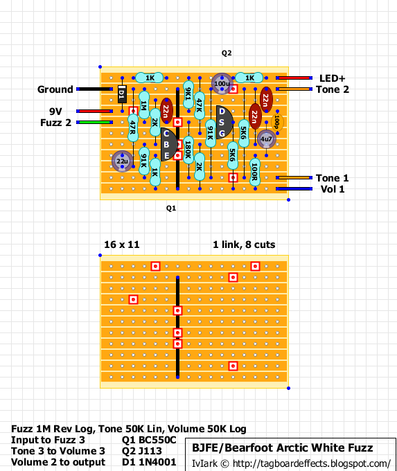
IvIark
- Tube Twister
Information
This is verified, thanks Matt
"If anyone is a 'genius' for putting jacks in such a pedal in the only spot where they could physically fit, then I assume I too am a genius for correctly inserting my legs into my pants this morning." - candletears7 - TGP
-
mmolteratx
- Degoop Doctor
Sold it and moved it on already.Seiche wrote:Am on my phone right now, so maybe I'm missing something, but where ist the 2n1308 on the AWF?
Edit: Nevermind, the AWF is on the right.
Matt, can you be so kind and provide the voltages of the transistors?
Yea, the one I had didn't have a ton of range either. It worked more as a boost knob, which makes sense seeing how its wired up. I'd try changing it into a SWTC by cutting the connection from the wiper of the tone pot to the R12/C5 junction.OnTheTundra wrote:I built it from the schematic and Ive found the tone pot doesnt have much range. Anyone else find anything similar? It does sound nice though.

-
mmolteratx
- Degoop Doctor
Connected between Q2 and Q3. EGDM is more like the PPF, but with a FET stage in place of the last transistor stage, and the germanium moved to Q2. Also has a passive tone control in addition to the PPF tone control between the 2nd and 3rd stages, and different filtering.ChargerSG wrote:Do you remember how those empty vertically positioned diodes connected in the circuit?
Here is a picture of the Emerald Green Guts
[ Image ]
Do you remember how they connected between Q2 and Q3 in the EGDM? It looks like one goes to ground? Could you also draw a rough schematic of the EGDM if you've traced it?
And I know the vertical ones aren't in the PPF, but they share the same boards hence the question. I meant to post this originally in the PPF
And I know the vertical ones aren't in the PPF, but they share the same boards hence the question. I meant to post this originally in the PPF
-
mmolteratx
- Degoop Doctor
Antiparallel to ground. I'll see if I can redraw the schem. The person who reversed it isn't 100% sure on a few things, but it looks mostly correct to me. Just need to ask for permission to post, or see if he'll post it here.ChargerSG wrote:Do you remember how they connected between Q2 and Q3 in the EGDM? It looks like one goes to ground? Could you also draw a rough schematic of the EGDM if you've traced it?
And I know the vertical ones aren't in the PPF, but they share the same boards hence the question. I meant to post this originally in the PPF
Okay I'd love to see a schematic if you could post it. I know the EGDM is described as "emulating what happens in the various stages of a vox" and "almost like it has a compressor built in" so I wonder if it referring to those diodesmmolteratx wrote:Antiparallel to ground. I'll see if I can redraw the schem. The person who reversed it isn't 100% sure on a few things, but it looks mostly correct to me. Just need to ask for permission to post, or see if he'll post it here.ChargerSG wrote:Do you remember how they connected between Q2 and Q3 in the EGDM? It looks like one goes to ground? Could you also draw a rough schematic of the EGDM if you've traced it?
And I know the vertical ones aren't in the PPF, but they share the same boards hence the question. I meant to post this originally in the PPF
-
mmolteratx
- Degoop Doctor
Nah, it's the same input stage as the PPF, with the same gain and tone controls. Into a Ge stage that's similar to the PPF's, then into a passive high end cut control exactly like the one in the DRD/antiparallel diodes to ground into a stage just like the first, but with a fixed resistor in series with the bypass cap and an 8k2 source resistor instead of a 14k7. Less low end passes between stages. The tone control, which is usually described as simulating speaker breakup, just controls the low end gain of the first stage and a low pass filter tacked on at the volume control simultaneously.ChargerSG wrote:Okay I'd love to see a schematic if you could post it. I know the EGDM is described as "emulating what happens in the various stages of a vox" and "almost like it has a compressor built in" so I wonder if it referring to those diodesmmolteratx wrote:Antiparallel to ground. I'll see if I can redraw the schem. The person who reversed it isn't 100% sure on a few things, but it looks mostly correct to me. Just need to ask for permission to post, or see if he'll post it here.ChargerSG wrote:Do you remember how they connected between Q2 and Q3 in the EGDM? It looks like one goes to ground? Could you also draw a rough schematic of the EGDM if you've traced it?
And I know the vertical ones aren't in the PPF, but they share the same boards hence the question. I meant to post this originally in the PPF