On bass guitar also?
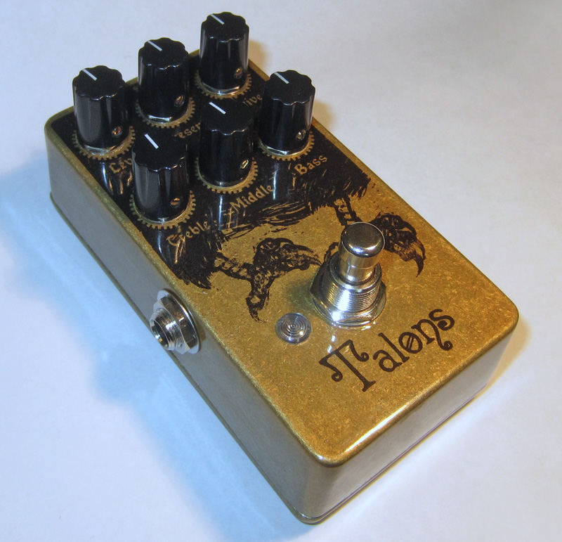
Earthquaker Devices - Talons [traced]
-
zedsnotdead

- Breadboard Brother
On bass guitar also?
-
andregarcia57
- Cap Cooler
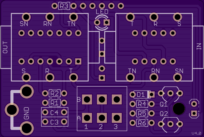
OSHPARK file-based layout storyboardist
I made some minor changes in layout. I prefer lying electrolyte.
unchecked.
I made some minor changes in layout. I prefer lying electrolyte.
unchecked.
- Attachments
-
- large_i.png (162.14 KiB) Viewed 3579 times
-
zedsnotdead
- Breadboard Brother
Holy 5hit John!! That's awesome!!!
Did you paint the enclosure yourself?
How did you get that image on the enclosure? It's the same as the original talons!
Good job my friend!
Did you paint the enclosure yourself?
How did you get that image on the enclosure? It's the same as the original talons!
Good job my friend!
-
andregarcia57
- Cap Cooler
-
johnk
- Resistor Ronker
thanks.zedsnotdead wrote:Holy 5hit John!! That's awesome!!!
Did you paint the enclosure yourself?
How did you get that image on the enclosure? It's the same as the original talons!
Good job my friend!
it's just a powder coated translucent gold enclosure with a decal and 4 coats of clear over it.

-
Visualdistortion

- Breadboard Brother
Really great, what brand of decal and clear coat did you use? I will love finish my pedal like this.
I wanna make it
I wanna make it wit chu
(again and again and again)
French... sorry
I wanna make it wit chu
(again and again and again)
French... sorry
-
andregarcia57
- Cap Cooler
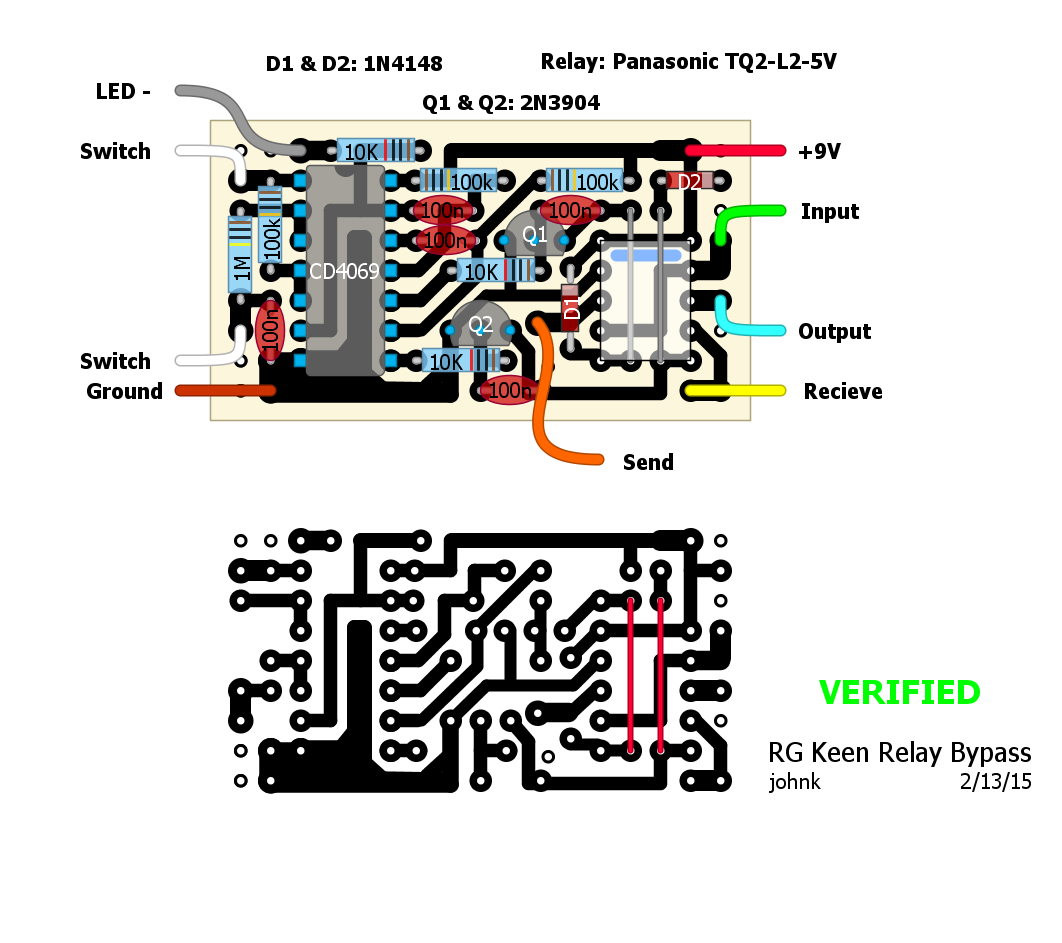
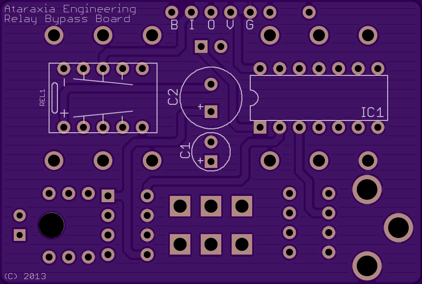
Relay
- Attachments
-
-
zedsnotdead
- Breadboard Brother
You know what would be really cool?
Designing a relay PCB that could be used with Moment-spdt pcb-mounted switches like these:

or these dpdt:

That would be uber cool!
BTW andregarcia, where can I find your design in OSH site?
Designing a relay PCB that could be used with Moment-spdt pcb-mounted switches like these:
or these dpdt:
That would be uber cool!
BTW andregarcia, where can I find your design in OSH site?
-
andregarcia57
- Cap Cooler
- Attachments
-
-
- 2.png (9.31 KiB) Viewed 3469 times
-
johnk
- Resistor Ronker
any good clear injet decal paper will work (I used VitaCal) and then used nitro lacquer over it, shot with a spray gun.Visualdistortion wrote: Really great, what brand of decal and clear coat did you use? I will love finish my pedal like this.
-
andregarcia57
- Cap Cooler
-
zedsnotdead
- Breadboard Brother
@andregarcia
have you read my message about the missing link? Havent heard from you...
There is a missing link on your PCB (OSHPark), one side of the clipping led pair is not connected to anything.
Cheers!
It's easy to overcome this, just solder a piece of wire on the back of the PCB linking 2 points, but I think I should mention it.
-
andregarcia57
- Cap Cooler
zedsnotdead wrote:@andregarcia
have you read my message about the missing link? Havent heard from you...
There is a missing link on your PCB (OSHPark), one side of the clipping led pair is not connected to anything.
Cheers!
It's easy to overcome this, just solder a piece of wire on the back of the PCB linking 2 points, but I think I should mention it.
hello ...
I think in the drive potentiometer, there really is no connection of the pins
-
mmolteratx
- Degoop Doctor
I did this one a long time ago. Meant for a 1590B, but you can fit it in most enclosure sizes with a bit of cleverness.
https://oshpark.com/shared_projects/yQKC4dyx
-
zedsnotdead
- Breadboard Brother
It's not the drive pot. That pot has pin3 unconnected, like in the schematic, and it's correct.
I am talking about the led pair.
Check the red line on the following image. That's the missing link.
I am talking about the led pair.
Check the red line on the following image. That's the missing link.
- Default.png (6.65 KiB) Viewed 3272 times
-
zedsnotdead
- Breadboard Brother
Brilliant!!!!mmolteratx wrote: I did this one a long time ago. Meant for a 1590B, but you can fit it in most enclosure sizes with a bit of cleverness.
https://oshpark.com/shared_projects/yQKC4dyx
Tks a lot mmolteratx!!