It's about time I contribute something to this forum. I tried myself at tracing my idiotboxeffects Blower Box. It's a great distortion box (both guitar and bass) and flavor-of-the-month over at talkbass.com. Turns out it is a RAT frontend with the Filter control replaced by a passive baxandall network. It'd be graet if someone could check the schematic against the pics or an actual unit, as this is my first trace. Anywho here is a link to the schematic and pix.
https://www.dropbox.com/sh/8pd6oq3mjhdv ... S_AJMwB2Fa
Idiotboxeffects - Blower Bass [traced]
-
mirosol

- Resistor Ronker
Great work p.eat!
I started to draw a stripboard layout for the circuit and i looking at the photos i noticed two things. First as a minor detail, i think the schematic is missing parallel polarity protection diode (1N400*) next to the 100µ filter cap. Second, the 1M resistor in parallel with volume control. I don't think that's a correct place for it. For all JFETs the gate needs to have a path to ground, usually via 1M or other relatively big value resistor. Otherwise the JFET will saturate and stop working in a minute or so.
Vero layout with 1M at gate to ground, series polarty protection and a trimmer for JFET drain coming up soon(ish)...
The design doesn't look bad at all. I'd say Idiotbox may be one of those where buying the original isn't a bad choice. Thanks for the trace again!
+m
http://tagboardeffects.blogspot.com/
http://mirosol.kapsi.fi/
"No such thing as innocence" -Iron Chic
http://mirosol.kapsi.fi/
"No such thing as innocence" -Iron Chic
-
mirosol
- Resistor Ronker
Here we go. With adjustments i mentioned above.
[update below]
[update below]
http://tagboardeffects.blogspot.com/
http://mirosol.kapsi.fi/
"No such thing as innocence" -Iron Chic
http://mirosol.kapsi.fi/
"No such thing as innocence" -Iron Chic
Hi Miro,mirosol wrote:Great work p.eat!
I started to draw a stripboard layout for the circuit and i looking at the photos i noticed two things. First as a minor detail, i think the schematic is missing parallel polarity protection diode (1N400*) next to the 100µ filter cap. Second, the 1M resistor in parallel with volume control. I don't think that's a correct place for it. For all JFETs the gate needs to have a path to ground, usually via 1M or other relatively big value resistor. Otherwise the JFET will saturate and stop working in a minute or so.
Vero layout with 1M at gate to ground, series polarty protection and a trimmer for JFET drain coming up soon(ish)...
The design doesn't look bad at all. I'd say Idiotbox may be one of those where buying the original isn't a bad choice. Thanks for the trace again!
+m
thanks for having a look and making a layout. There is indeed a polarity protection diode. It's there in my hand scetch, I just forgot to include it in eagle fp . I also wondered about the 1M in parallel to the volume control as it's useless in that spot. I'll have to pop the box open again and have a look. In reviewing my hand notes: I also forgot a 100pF cap across D and G of the J201.
I know JohnK has one. Maybe he can have a look in his?
-
mirosol
- Resistor Ronker
I Added that 100p, and it makes sense as there are other noise reduction measures in use too.
About the 1M. It is present in every Rat and derivative schematic between gate and ground. I happen to know for a fact that JFETs won't work without it :) Let's just say that i've made that design error in some of mine... I posted the layout on the blog too, so i think we'll see rather quickly if it works.
[Updated below]
http://tagboardeffects.blogspot.com/
http://mirosol.kapsi.fi/
"No such thing as innocence" -Iron Chic
http://mirosol.kapsi.fi/
"No such thing as innocence" -Iron Chic
-
mirosol
- Resistor Ronker
Damn i hate it when i try to beat every other layouter to a new schematic :) Here's one more, with one obvious, idiotic error fixed.
- Attachments
-
http://tagboardeffects.blogspot.com/
http://mirosol.kapsi.fi/
"No such thing as innocence" -Iron Chic
http://mirosol.kapsi.fi/
"No such thing as innocence" -Iron Chic
-
johnk

- Resistor Ronker
I just looked at mine and the source resistor is definitely a 1K5.
and there is no resistor connected from the drain to ground. the only components connected to the drain are the 10u & 100p caps.
I measured the voltage at the drain on mine with a 9.02V power supply and it reads 8.17V.
and there is a 1 meg resistor from the volume pot's lug 3 to ground.
and there is no resistor connected from the drain to ground. the only components connected to the drain are the 10u & 100p caps.
I measured the voltage at the drain on mine with a 9.02V power supply and it reads 8.17V.
and there is a 1 meg resistor from the volume pot's lug 3 to ground.
-
mirosol
- Resistor Ronker
No. I've said it twice. 1M needs to be between gate and ground, not drain and ground.
A few examples:
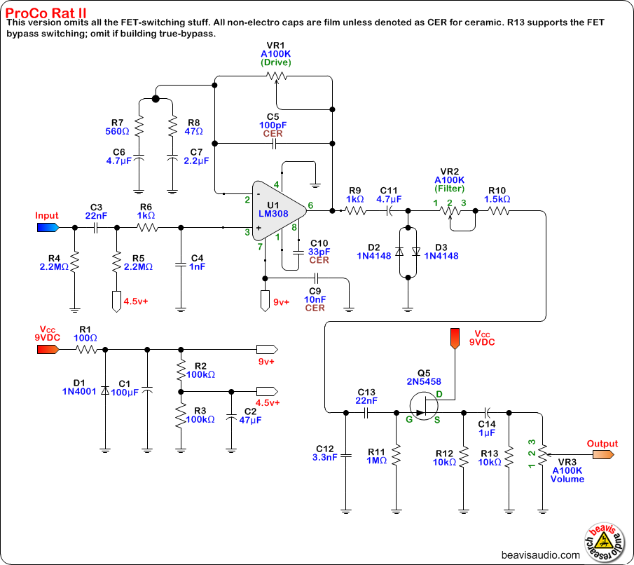
http://www.beavisaudio.com/schematics/I ... ematic.png
http://www.dirk-hendrik.com/temp/ibanez ... _metal.pdf
http://www.dirk-hendrik.com/proco_rat.pdf
http://www.electrosmash.com/proco-rat
If you look at any schematic with a FET, you'll see there's a resistor in that position.
Main difference with Blowerbox is that the JFET is common source amplifier, not a buffer. But it will still need a path to ground from gate in both cases.
In parallel with volume control, 1M will simply make the taper slightly steeper, but it won't affect anything else.
Source resistor is 1,5K in the images too.
+m
A few examples:
http://www.beavisaudio.com/schematics/I ... ematic.png
http://www.dirk-hendrik.com/temp/ibanez ... _metal.pdf
http://www.dirk-hendrik.com/proco_rat.pdf
http://www.electrosmash.com/proco-rat
If you look at any schematic with a FET, you'll see there's a resistor in that position.
Main difference with Blowerbox is that the JFET is common source amplifier, not a buffer. But it will still need a path to ground from gate in both cases.
In parallel with volume control, 1M will simply make the taper slightly steeper, but it won't affect anything else.
Source resistor is 1,5K in the images too.
+m
http://tagboardeffects.blogspot.com/
http://mirosol.kapsi.fi/
"No such thing as innocence" -Iron Chic
http://mirosol.kapsi.fi/
"No such thing as innocence" -Iron Chic
-
johnk
- Resistor Ronker
well, there's definitely not a 1M from gate to ground in this pedal. I just traced it out in mine.
here's a pic of a mirror image of the bottom of the board with the component labels on it as they are on top of the board. you can clearly see that there isn't a 1M from the gate to ground:
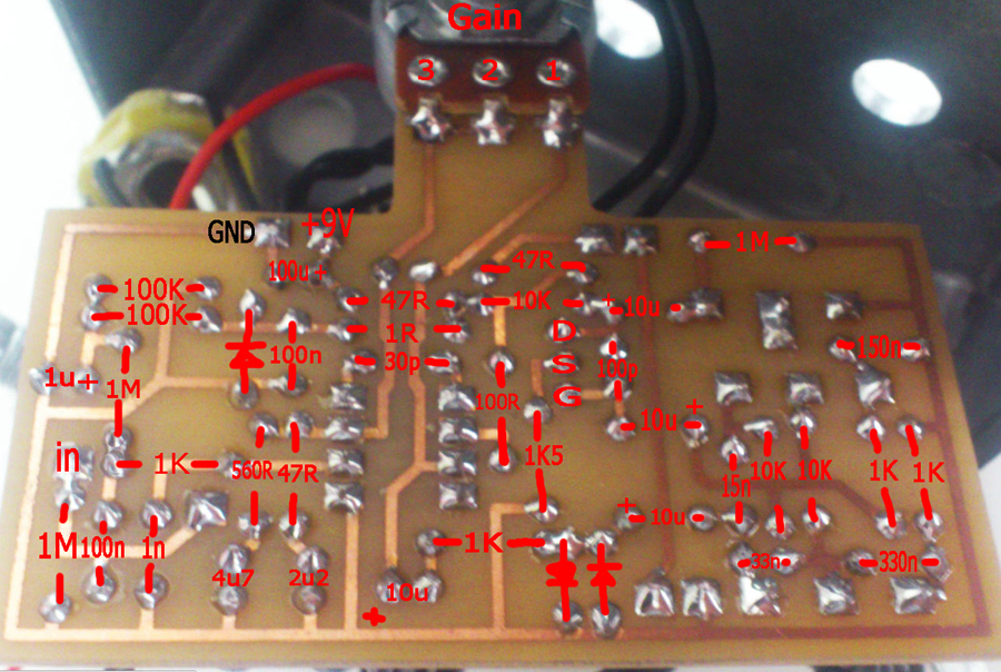
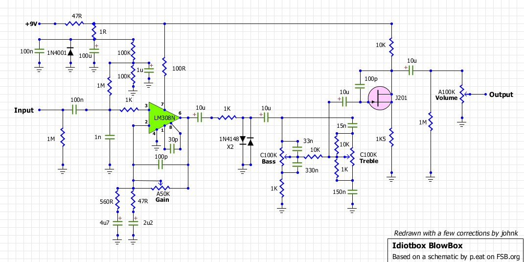
and here's a schematic of it that I redrew using p.eat's but with corrections:
here's a pic of a mirror image of the bottom of the board with the component labels on it as they are on top of the board. you can clearly see that there isn't a 1M from the gate to ground:
and here's a schematic of it that I redrew using p.eat's but with corrections:
-
mirosol
- Resistor Ronker
Ah. That explains it. Thanks John. The p.eat's schematic dumps everything to ground through the clippers as there's no decoupling before them. That may be the biggest issue. I'll redraw the layout later tonight per these corrections.
However. The missing 1M from gate should definitely be there. I'm thinking that's a design error.
+m
However. The missing 1M from gate should definitely be there. I'm thinking that's a design error.
+m
http://tagboardeffects.blogspot.com/
http://mirosol.kapsi.fi/
"No such thing as innocence" -Iron Chic
http://mirosol.kapsi.fi/
"No such thing as innocence" -Iron Chic
-
johnk
- Resistor Ronker
well, it just may be a design error, but it definitely works without it and the original pedal sounds great.mirosol wrote: However. The missing 1M from gate should definitely be there. I'm thinking that's a design error.
+m
-
mirosol
- Resistor Ronker
Here we go, one last time :) Apparently the missing cap was the only real issue. I'm not sure if this is how John fixed his board, but i'm quite confident about the layout now...
I'm still taking the 1M from gate to ground instead of having it parallel with the volume control.
I'd like to click collective thumbs up for forum moderators...
I'm still taking the 1M from gate to ground instead of having it parallel with the volume control.
I'd like to click collective thumbs up for forum moderators...
- Attachments
-
http://tagboardeffects.blogspot.com/
http://mirosol.kapsi.fi/
"No such thing as innocence" -Iron Chic
http://mirosol.kapsi.fi/
"No such thing as innocence" -Iron Chic
-
GodSaveMetal
- Resistor Ronker
johnk wrote:well, there's definitely not a 1M from gate to ground in this pedal. I just traced it out in mine.
here's a pic of a mirror image of the bottom of the board with the component labels on it as they are on top of the board. you can clearly see that there isn't a 1M from the gate to ground:
[ Image ]
and here's a schematic of it that I redrew using p.eat's but with corrections:
[ Image ]
Please post the layout, PCB and BOM of this excelent pedal!!! THANKS man it´s great!
-
johnk
- Resistor Ronker
I made mine from the veroboard, so sorry I don't have a PCB layout or BOM.GodSaveMetal wrote: Please post the layout, PCB and BOM of this excelent pedal!!! THANKS man it´s great!
Hi JohnK,
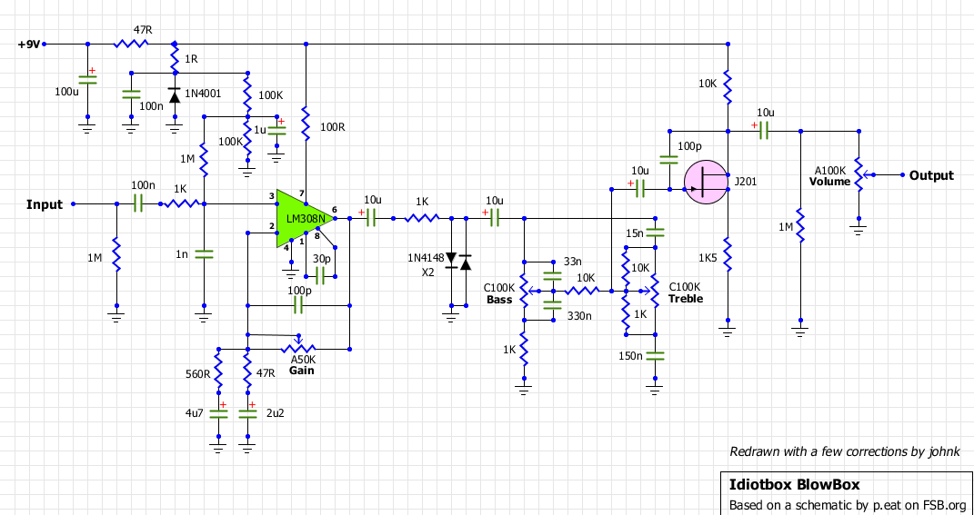
thanks for posting the updated schematic and the pic of the bottom of the board. I am really new to building effect pedals and electronics in general but I think there are two small inaccuracies. Attached you can find an image of what seems wrong to me...
thanks for posting the updated schematic and the pic of the bottom of the board. I am really new to building effect pedals and electronics in general but I think there are two small inaccuracies. Attached you can find an image of what seems wrong to me...
- Attachments
-
- BlowerBox_Schematic_mod.png (13.77 KiB) Viewed 4556 times
-
mirosol
- Resistor Ronker
The filter cap position doesn't affect the operation too much as there are other noise reduction methods in use too. The location of VRef for the opamp input on the other hand may affect something..
Thankfully that was very easy fix for the layout.
Thankfully that was very easy fix for the layout.
- Attachments
-
http://tagboardeffects.blogspot.com/
http://mirosol.kapsi.fi/
"No such thing as innocence" -Iron Chic
http://mirosol.kapsi.fi/
"No such thing as innocence" -Iron Chic