Kingsley - Page (gutshots) [traced]
Can someone help me tracing the kingsley page tube boost. I only have Gutshots from the internet. Hope someone can help me. Thank you.
- Attachments
-
-
Manfred

- Tube Twister
Information
- Posts: 1945
- Joined: 04 Apr 2009, 23:42
- Has thanked: 1675 times
- Been thanked: 1360 times
It is not possible to find out the circuit by tracing, the shown wiring in the forground are incomplete
and the other in in the background is not clearly visible.
and the other in in the background is not clearly visible.
Here are some shots inside
- Attachments
-
-
Manfred
- Tube Twister
Information
- Posts: 1945
- Joined: 04 Apr 2009, 23:42
- Has thanked: 1675 times
- Been thanked: 1360 times
Sorry, I would like to do the trace, but also to many unvisible things in the last shot to me.

I know this isn't useful in the slightest, but I thought it might be fun to see what information was actually present in the photos, so I did my best. I'm not 100% on the resistor values. You would need a lot more photos from a lot more angles to actually get close to a schematic. I think the bottom side of what has arbitrarily named R2 goes to ground, as it appears to go to the switch to participate in the LED part of the circuit, but who knows.
I appreciate your efforts. It is so hard to traced na pedals without full gutshots. I hope someone kind enough who has this pedal to share some more photos so we can trace this awesome pedal.
-
Ice-9

- Degoop Doctor
Information
Here is an idea, If it is a pedal you really need then maybe buy one, work out the schematic yourself and post it here as many others do, make one then sell on the original to recoup your cost.johngovan1234 wrote:I appreciate your efforts. It is so hard to traced na pedals without full gutshots. I hope someone kind enough who has this pedal to share some more photos so we can trace this awesome pedal.
It's fairly straight forward, if you want to start it , press start. You can work out the rest of the controls for yourself !
No silicon heaven ? preposterous ! Where would all the calculators go ?
No silicon heaven ? preposterous ! Where would all the calculators go ?
-
ppluis0

- Diode Debunker
Same as the tracer fund used to be here at the forum: buy-degoop-publish schems-sellIce-9 wrote:Here is an idea, If it is a pedal you really need then maybe buy one, work out the schematic yourself and post it here as many others do, make one then sell on the original to recoup your cost.
Cheers,
Jose
-
Manfred
- Tube Twister
Information
- Posts: 1945
- Joined: 04 Apr 2009, 23:42
- Has thanked: 1675 times
- Been thanked: 1360 times
Same as the tracer fund used to be here at the forum: buy-degoop-publish schems-sell
I did often in this way.
-
modman

- a d m i n
Information
- Posts: 4898
- Joined: 19 Jun 2007, 16:57
- Has thanked: 4411 times
- Been thanked: 2139 times
Ah them good ole days... well, right now we are looking at upgrading the server in order to avoid outage like we had last week and trying to pull the forum into the new decade. Databases have grown massive and need cleaning, so we are working on that first. That's the prime reason I set up the Patreon page, but once works are done, prices of new servers leases become predictable, we may be able to dabble into that again. But I'm not promising anything at this point, was thinking a lot about it but right now there are other priorities.Manfred wrote:Same as the tracer fund used to be here at the forum: buy-degoop-publish schems-sell
I did often in this way.
And remember we've had pedals getting traced from pictures posted 7 years earlier...
Please, support freestompboxes.org on Patreon for just 1 pcb per year! Or donate directly through PayPal
-
modman
- a d m i n
Information
- Posts: 4898
- Joined: 19 Jun 2007, 16:57
- Has thanked: 4411 times
- Been thanked: 2139 times
Thanks pluis! Don't hesitate to steal properly and attach pictures when the pedal's not fully traced yet...
This gut shot show that besides the rustic 50s tube tagboard part there is a Chinese pcb style power section ...
This gut shot show that besides the rustic 50s tube tagboard part there is a Chinese pcb style power section ...
- Screen Shot 2020-01-21 at 23.27.11.png (105.48 KiB) Viewed 4608 times
Please, support freestompboxes.org on Patreon for just 1 pcb per year! Or donate directly through PayPal
-
Intripped

- Cap Cooler
I'm quite sure that this circuit is a pre-made voltage multiplier.
this pedal has an external dc power supply:
"The 9VDC power supply (provided) is converted to both 6.3VDC for the tube heaters and 250VDC for the tube plates."
"Power requirements: 9VDC @ 500mA, center negative, 2.1mm jack"
this pedal has an external dc power supply:
"The 9VDC power supply (provided) is converted to both 6.3VDC for the tube heaters and 250VDC for the tube plates."
"Power requirements: 9VDC @ 500mA, center negative, 2.1mm jack"
-
ppluis0
- Diode Debunker
You're right Intripped. This kind of switch mode voltage elevator appears in other tube pedals here at the forum.Intripped wrote:I'm quite sure that this circuit is a pre-made voltage multiplier.
An example can be this diagram:

I have draw a partial schematic of this pedal based on the pictures of this thread. Let me clean up a bit and will post soon
Cheers,
Josè
-
ppluis0
- Diode Debunker
Hi folks,
Preliminary drawing !!!
I'm not completely sure about tone pot connections. Also there is an 1Meg resistor from pin 2 of the tube to gnd that I forget to draw.
Some connections were evident in the pictures and some others were guessed and drawing using common sense, so take this diagram with caution
The step up supply board is assumed similar to those that appear in the above post, so isn't included in the audio section.
That supply board is feed directly from the DC jack (an almost-hidden yellow wire in one picture...) to one tag and through a small axial coil.
Also, the heater of the tube is supposed to be connected directly to the same DC jack to avoid heavy current in the audio gnd.
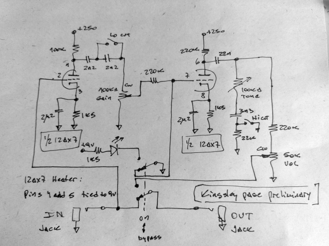
Cheers,
Jose
Preliminary drawing !!!
I'm not completely sure about tone pot connections. Also there is an 1Meg resistor from pin 2 of the tube to gnd that I forget to draw.
Some connections were evident in the pictures and some others were guessed and drawing using common sense, so take this diagram with caution
The step up supply board is assumed similar to those that appear in the above post, so isn't included in the audio section.
That supply board is feed directly from the DC jack (an almost-hidden yellow wire in one picture...) to one tag and through a small axial coil.
Also, the heater of the tube is supposed to be connected directly to the same DC jack to avoid heavy current in the audio gnd.
Cheers,
Jose
- Attachments
-
- Kingsley Page preliminary drawing
-
brejna
- Breadboard Brother
Yesterday I was tracing from pics and I draw exactly the same layout/schematic, except I think gain pin 2 should be grounded not after 220k. From other kingsley pedals maybe cathode bypass caps are 150n? Also gain should be A500k.
Also kingsley uses 6v3 heaters..
Also kingsley uses 6v3 heaters..
-
ppluis0
- Diode Debunker
Hi Brejna,
You're right !! The coaxial cable from the pushbutton is soldered to the mid tag on the gain pot and from this node depart the 220K to the grid.
I did some time ago a test feeding the heater of a 12AX7 with 9vdc to pins 4 and 5 (leaving pin 9 unconnected) and the current measured was 127mA instead of the nominal 150mA when the tube is running at 12.6V and this is due the positive temperature coefficient of the filament itself.
If the filament were a perfect resistor (of 84 ohms) then the current will drop to 107mA @ 9V
In this same way the Hermida Zendrive 2 feeds a 12AX7 with 9vdc.
Regarding the values of the potentiometers, they are visible in the partially assembled units showed at the first post. I also think I have read 225 in one of those cathode capacitors of the same image, but can't be completely sure.
Cheers,
Jose
You're right !!
I did some time ago a test feeding the heater of a 12AX7 with 9vdc to pins 4 and 5 (leaving pin 9 unconnected) and the current measured was 127mA instead of the nominal 150mA when the tube is running at 12.6V and this is due the positive temperature coefficient of the filament itself.
If the filament were a perfect resistor (of 84 ohms) then the current will drop to 107mA @ 9V
In this same way the Hermida Zendrive 2 feeds a 12AX7 with 9vdc.
Regarding the values of the potentiometers, they are visible in the partially assembled units showed at the first post. I also think I have read 225 in one of those cathode capacitors of the same image, but can't be completely sure.
Cheers,
Jose
-
John G
- Breadboard Brother
Hi,
First photo shows, at the extreme right hand end a 10Meg ohm to a ground.
The top end has the input coax connected, and most probably a 33K ohm resistor going up to the first grid.
This is NOT a true bypass design as the input to the tube is across the signal path at all times.
John
First photo shows, at the extreme right hand end a 10Meg ohm to a ground.
The top end has the input coax connected, and most probably a 33K ohm resistor going up to the first grid.
This is NOT a true bypass design as the input to the tube is across the signal path at all times.
John