Aaahh, so that could be 'sapping' some of the power then, right? Thanks!Fuzzer wrote:Well, 914's eat like .5 more volts than the schottkys.
Lovepedal - Purple Plexi 800 [goop-alarm] [traced]
Great Fuzzer, thanks. I'll order some BAT46s. Just out of curiosity, are all Schottkys "created equally?" Small Bear has some 5158s (or something like that I forget). Or do those have different forward voltages (or whatever).Fuzzer wrote:Sure, and those 386 don't like that sag.
Lastly, I do have a variety of different diodes around so are there any others that don't cause the sag as much? I tired some 1N34 Ge ones, but they were about the same.
Thanks.
Well, I have used the ones you mentioned in my builds for protection and they don't eat more than 0.2 [V].
The thing that bugs me is that a germanium one didn't gave you better performance..., you should just try it without the diode. Because if it continues behaving badly then the cause will not be the diode at all.
The thing that bugs me is that a germanium one didn't gave you better performance..., you should just try it without the diode. Because if it continues behaving badly then the cause will not be the diode at all.
The Freestompboxes Forum search function is soo great, use the search function..., the S E A R C H function.
Jumper it is, good to know! I'll give it a shot. ThanksFuzzer wrote:Well, I have used the ones you mentioned in my builds for protection and they don't eat more than 0.2 [V].
The thing that bugs me is that a germanium one didn't gave you better performance..., you should just try it without the diode. Because if it continues behaving badly then the cause will not be the diode at all.
- briggs
- Tube Twister
Information
A protection diodes wired this way limits the current flow to the circuit and reduce the supply voltage a bit too. Dropping the diodes can alter the sound (esp. in battery powerd circuits) acc. to the circuit more or less.briggs wrote:The diodes could actually be removed, they are there for polarity protection, not really to alter the sound in any specific manner...
I recommend an A/B listening test to get an idea what will soundwise happen w and w/o those diodes.
JHS
- analogguru
- Old Solderhand
Information
A protection diodes wired this way limits the current...
analogguru
There´s a sucker born every minute - and too many of them end up in the bootweak pedal biz.
- Dirk_Hendrik
- Old Solderhand
Information
jeez AG... do we have to spell out everything for you??? 
Just the same as in, for instance, the ADA flanger input stage. There's a diode limiter there. So, conclusion, diodes limit! Since they have a fixed forward bias voltage that cannot be changed it must be the curent that's doing the limiting. Simple....
JHS,
Same question as AG asks above.
Elaborate this interesting limiting remark.
- analogguru
- Old Solderhand
Information
Thats a good attempt  , but I am a little bit confused now:
When the current is limited by the diode, why the protection diode always gets destroyed when I connect reverse polarity to a pedal ?
analogguru
When the current is limited by the diode, why the protection diode always gets destroyed when I connect reverse polarity to a pedal ?
analogguru
There´s a sucker born every minute - and too many of them end up in the bootweak pedal biz.
- Dirk_Hendrik
- Old Solderhand
Information
Crap... here we go, freshyear electronics lesson2 (1 was about light bulbs)
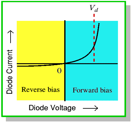
As you may remember this is the standard forward bias voltage curve of a diode:

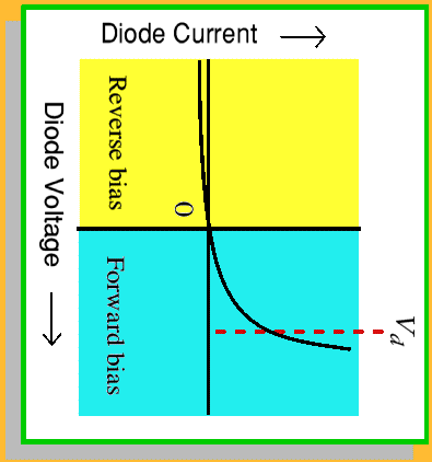
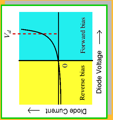
Because a symmetric (non AC biased) sinewave travels all 4 quadrants this curve will, depeding on which quadrant the sine wave is in alter with the wave:


What you definitely will notice in these 4 curves is that the current remains independent of the voltage which still supports the undoubtful fact that there's current limiting in place.
The fact that your diodes fail is probably due to the forward voltage vs reversed current regulations in some parts of the world. That doesn't have anything to do with diode limiting. A simple DC/CD inverter should cure that problem in no time.
have luck.
As you may remember this is the standard forward bias voltage curve of a diode:

Because a symmetric (non AC biased) sinewave travels all 4 quadrants this curve will, depeding on which quadrant the sine wave is in alter with the wave:


What you definitely will notice in these 4 curves is that the current remains independent of the voltage which still supports the undoubtful fact that there's current limiting in place.
The fact that your diodes fail is probably due to the forward voltage vs reversed current regulations in some parts of the world. That doesn't have anything to do with diode limiting. A simple DC/CD inverter should cure that problem in no time.
have luck.
Sure, the diodes aren't there for sonic purposes, but still better safe and put some kind of protection, I just don't suggest the reverse diode from +V to ground, I have never liked that.briggs wrote:The diodes could actually be removed, they are there for polarity protection, not really to alter the sound in any specific manner...
The Freestompboxes Forum search function is soo great, use the search function..., the S E A R C H function.
- nooneknows
- Resistor Ronker
I have an OCD clone, that I love, and I'm using it with a stratocaster in my Peavey Classic 30 (clean channel) or in my JCM 800 combo single channel, both sound great.chris_d wrote:Folks who like this one, and/or the OCD, what amps are you running through?
due to the tech getting the best of me
i have sweepped a clone and a real PP800 on a spectrum analyzer...
i set the controls about mid range.
sweep from 20hz to 20khz.
the first one is the clone and the second one is the real deal.
i have to admit i can not tell you what the difference is but there is a small difference...
peace minatour87
- Attachments
-
 Chart2.pdf
- (8.15 KiB) Downloaded 460 times
-
 Chart1.pdf
- (8 KiB) Downloaded 314 times
- Ghandi
- Solder Soldier
I know that, look who did reverse engineering. 
I'm asking minatour87 if he used the third 47uF cap on the clone he tested!?
...since there are some schematics which don't show that cap...
I'm asking minatour87 if he used the third 47uF cap on the clone he tested!?
...since there are some schematics which don't show that cap...
If you look at the pictures in page 1, you see that there are also 3 elco's.Ghandi wrote:I know that, look who did reverse engineering.
I'm asking minatour87 if he used the third 47uF cap on the clone he tested!?
...since there are some schematics which don't show that cap...
Somebody made a remark of that.
But if you leave it out, it isn't a big deal.
It's just to filter the power.
- Ghandi
- Solder Soldier
@Jimmy-H,
I know I made the remark on page 1.
the 3 elco's are the 3 47uF caps I'm talking about!
0,1uF and 47,1uF filtering makes a difference I hear (at least) in a blind test
and it could also easily explain the difference minatour87 measured with his septrum clone and a real PP800 on his spectrum analyzer.

