Sorry for mistake guys...
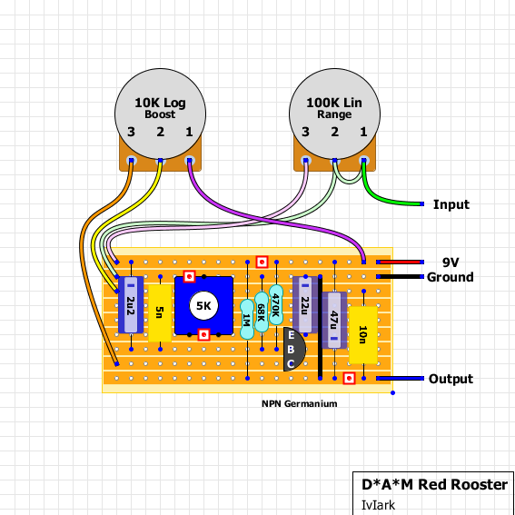
D*A*M - Red Rooster
-
beedotman

- Diode Debunker
Information
OK... fixed layouts!
Sorry for mistake guys...
Sorry for mistake guys...
- Attachments
-
-
 rr-09.pdf
- (65.53 KiB) Downloaded 139 times
-
-
- rr-09_npn.pdf
- (65.5 KiB) Downloaded 151 times
http://www.turretboard.org 4 life!
-
sinner

- Old Solderhand
Information
- Posts: 4709
- Joined: 06 Nov 2008, 17:16
- Location: ...no more
- Has thanked: 1031 times
- Been thanked: 909 times
I still think LED wiring for NPN version is not right
-
beedotman
- Diode Debunker
Information
Why? 
In NPN D*A*M stomps switch is wired in the same way....
In NPN D*A*M stomps switch is wired in the same way....
- Attachments
-
http://www.turretboard.org 4 life!
-
sinner
- Old Solderhand
Information
- Posts: 4709
- Joined: 06 Nov 2008, 17:16
- Location: ...no more
- Has thanked: 1031 times
- Been thanked: 909 times
Looks like LED takes 9V, it's not limited by the resistor.
-
phibes

- Transistor Tuner
Information
It's right. The limiting resistor can be on either side. Doesn't matter if it's on 9v or ground.sinner wrote:Looks like LED takes 9V, it's not limited by the resistor.
GuitarlCarl - "TGP = The Gear Polishers"
 Ken
Ken
Ken-
beedotman
- Diode Debunker
Information
So it's correct! Thanks!phibes wrote:It's right. The limiting resistor can be on either side. Doesn't matter if it's on 9v or ground.sinner wrote:Looks like LED takes 9V, it's not limited by the resistor.
http://www.turretboard.org 4 life!
-
beedotman
- Diode Debunker
Information
Very cool!G5120fx wrote:Works perfect now!
Thx b!
Try also lower input 2u2 cap to let say 100nF and increase 10nF to 100nF on output.
http://www.turretboard.org 4 life!
The output level is a LINEAR pot? In this layout is a LOG pot... Am I missing something?
http://4.bp.blogspot.com/-9YoCXJc9x00/T ... rected.png
http://4.bp.blogspot.com/-9YoCXJc9x00/T ... rected.png
-
beedotman
- Diode Debunker
Information
I think both are linears, but I'm not 100% sure. Lin or Log - it isn't really big difference...FrankKair wrote:The output level is a LINEAR pot? In this layout is a LOG pot... Am I missing something?
http://4.bp.blogspot.com/-9YoCXJc9x00/T ... rected.png
http://www.turretboard.org 4 life!
-
JVanDe7
- Resistor Ronker
Information
- Posts: 333
- Joined: 26 Apr 2008, 18:49
- Completed builds: DAM Red Rooster clone, Zvex Octane 3 clone, Zvex Fuzz Factory clone, Maestro MFZ-1 clone, Fulltone Soul Bender clone, Fulltone 69 clone, Green Russian Muff clone, Dallas Rangemaster clone, Mosrite Fuzzrite clone, EA Tremolo, VOX Clyde McCoy wah, Jordan Bosstone clone, Analogman Sun Face clone...
- Has thanked: 21 times
- Been thanked: 10 times
I built mine with 10K LOG and 100K Linear and it sweeps very nice on both.
Although... the 10K LOG boost knob is only usable after 12 o'clock. I don't mind that at all though. It hits unity level around 12 or 1 o 'clock if I recall correctly. But there are probably other factors involved besides audio or linear taper pot.
Although... the 10K LOG boost knob is only usable after 12 o'clock. I don't mind that at all though. It hits unity level around 12 or 1 o 'clock if I recall correctly. But there are probably other factors involved besides audio or linear taper pot.
“Walk tall, kick ass, learn to speak Arabic, love music and never forget you come from a long line of truth seekers, lovers and warriors.”
― Hunter S. Thompson
― Hunter S. Thompson
Hi Guys,
Going to take a stab at this booster. Does anyone know where I can get some decent transistors for it. Many tanks
Joseph
Going to take a stab at this booster. Does anyone know where I can get some decent transistors for it. Many tanks
Joseph
-
beedotman
- Diode Debunker
Information
Try CV7355 - usually pretty high gain, but low leakage at the same time, sounds really great in boosters (they were used in Red Roosters as well) and are cheap.clusterstudios wrote:Hi Guys,
Going to take a stab at this booster. Does anyone know where I can get some decent transistors for it. Many tanks
Joseph
You can buy 10 pieces for 15GBP, here for example (great transistor seller by the way):
https://www.ebay.com/itm/2N1309-CV7355- ... 3cc8efb182
http://www.turretboard.org 4 life!
-
beedotman
- Diode Debunker
Information
These sounds great - CV7003 (military version of OC44) - Analogman is using them in Beano Boost.
Same seller, but 7GBP for a piece...:
https://www.ebay.com/itm/OC44-CV7003-TI ... 483a255923
Same seller, but 7GBP for a piece...:
https://www.ebay.com/itm/OC44-CV7003-TI ... 483a255923
http://www.turretboard.org 4 life!
-
beedotman
- Diode Debunker
Information
-
Dr Tony Balls

- Diode Debunker
I make em with soviet MP38As all the time
-
gilmour_pugliese
- Resistor Ronker
hi guys, it's possible to replace the range pot with a 250k lin, without any difference in tone?
-
beedotman
- Diode Debunker
Information
Resistance could be to big, you can try, maybe it will suit You.gilmour_pugliese wrote:hi guys, it's possible to replace the range pot with a 250k lin, without any difference in tone?
You can also put 220K resistor across pot lugs that You will be using to achieve around 100K pot resistance.
http://www.turretboard.org 4 life!
-
beedotman
- Diode Debunker
Information
Resistor on pot should be around lug 3 and 2 since on 2 and 1 it had jumper.
http://www.turretboard.org 4 life!
-
gilmour_pugliese
- Resistor Ronker
Thanks man!beedotman wrote:Resistor on pot should be around lug 3 and 2 since on 2 and 1 it had jumper.