Xotic - AC Booster [ goop-alarm ] [traced]

Information
- Posts: 7
- Joined: 11 Sep 2007, 16:12
Realy Realy good job I think it was same as TS? + Mod Treble and Bass?
-
The Rotagilla

- Diode Debunker
Well the AC has finally been knocked off my board as my main OD. I'll get to work on labeling the pads for the off board connections. I should be able to have it done by next weekend. If there's anything not clearly indentifiable in the previous pictures, please let me know and I'll confirm.
-
The Rotagilla
- Diode Debunker
Well next weekend is here and I've made little progress. As I stated earlier, I destroyed the factory IC installing the socket so I contacted Xotic and got a replacement. The ID numbers were sanded off the replacement as well, but not completely. I was able to make out the following...
45--D
RC
I'm going to guess the stock IC is a JRC 4558D. When I installed an extra 4558D I had, it sounded the same as the one they sent me. I'd say one more question answered.
45--D
RC
I'm going to guess the stock IC is a JRC 4558D. When I installed an extra 4558D I had, it sounded the same as the one they sent me. I'd say one more question answered.
JHS, your links don't seem to be working. Can you fix them?
Thanks!
Thanks!
JHS wrote:
REV: A
... a bit closer to the org. thing but w/o trannie and IC specs useless as before.
JHS
I increased the input cap on my AC to .056uF for more meat and increased the pico cap in the IC's FB loop to 220pF for a little more rounding. I also lowered the last resistor in line to 100 Ohms (CC) for even greater mojo.
-
Lovepedal Detective

- Breadboard Brother
Very Cool. Thanks for the work on this one.
LP
LP
-
The Rotagilla
- Diode Debunker
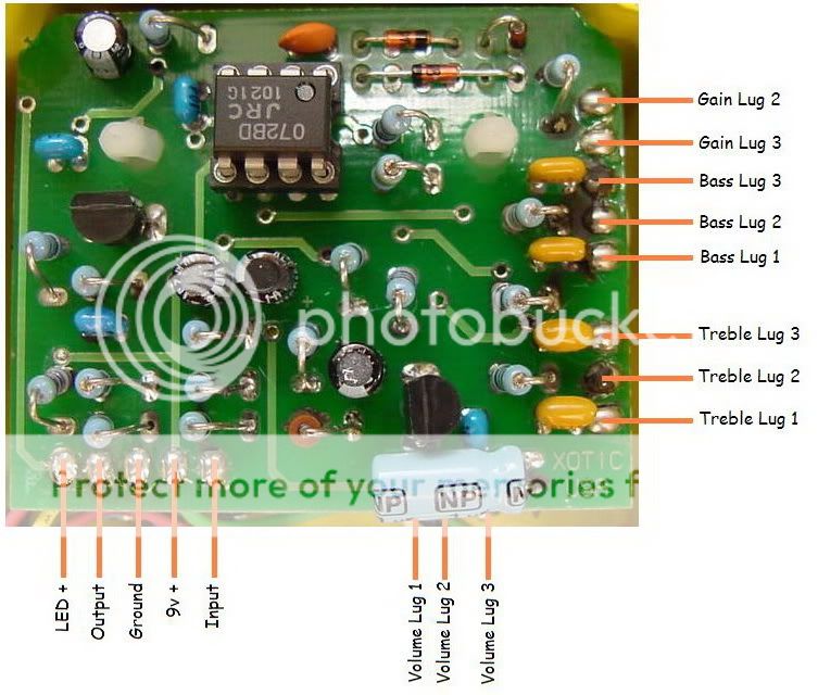
Long overdue and I do apologize. Photo notes -
1) There are three pads under the 1uF NP for the Volume control.
2) I'm going to revise my statement about the stock IC. After staring at the replacement Xotic sent me under a bright light until my head hurt, I'm going to say it might be a JRC4557D.
3) Direct Photo Link
I have not compared this to the existing schematic. Hopefully someone has enough info now to do a layout.
-
bajaman

- Old Solderhand
Information
- Posts: 4549
- Joined: 26 Jun 2007, 21:18
- Location: New Brighton, Christchurch, NZ
- Has thanked: 596 times
- Been thanked: 2061 times
nice hi res picture Rota 

bajaman
bajaman
Has anyone (here) completed the AC Booster schematic? The 'RotaXotic' Drive that is up is lacking a few components that are on the circuit board - not quite completed.
A better understanding of what each component on the board is responsible for would greatly help personalization of this circuit.
Thanks.
A better understanding of what each component on the board is responsible for would greatly help personalization of this circuit.
Thanks.
-
The Rotagilla
- Diode Debunker
First page of this thread contains a component labled pic.gtrwrks wrote:Has anyone (here) completed the AC Booster schematic? The 'RotaXotic' Drive that is up is lacking a few components that are on the circuit board - not quite completed.
A better understanding of what each component on the board is responsible for would greatly help personalization of this circuit.
Thanks.
Information
- Posts: 5
- Joined: 07 Feb 2008, 11:03
hi. i'm ranmusic84 from Japan.
sorry for my bad english.
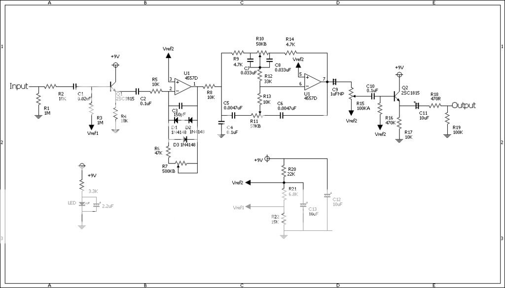
i made AC booster schematic from Rota's photo and ts-808 schematic.
if there's some mistake, point them.
i have no confidence that the transistors are 2sc1815. bet this transintor are used in BB preamp.
https://i251.photobucket.com/albums/gg2 ... OOSTER.jpg
sorry for my bad english.
i made AC booster schematic from Rota's photo and ts-808 schematic.
if there's some mistake, point them.
i have no confidence that the transistors are 2sc1815. bet this transintor are used in BB preamp.
https://i251.photobucket.com/albums/gg2 ... OOSTER.jpg
-
soulsonic

- Old Solderhand
Information
Hello. Welcome to the forum!ranmusic84 wrote: if there's some mistake, point them......
https://i251.photobucket.com/albums/gg2 ... OOSTER.jpg
I see a small mistake. There should be a resistor connected between Q1 Emitter and common ground. Without this, there will be no sound.
Thank you for your work.
"Analog electronics in music is dead. Analog effects pedal design is a dead art." - Fran
Information
- Posts: 5
- Joined: 07 Feb 2008, 11:03
Oops! thank you for telling!soulsonic wrote:I see a small mistake. There should be a resistor connected between Q1 Emitter and common ground. Without this, there will be no sound.
I've fixed the mistake and updated the file.
https://i255.photobucket.com/albums/hh1 ... OOSTER.jpg
-
The Rotagilla
- Diode Debunker
Welcome and nice work.
I'm fairly certain the op amp is a JRC4557D. Is your schematic a Tube Screamer that's been AC Booster'd or are you fairly confident that it corresponds to the photos? Thanks again.
I'm fairly certain the op amp is a JRC4557D. Is your schematic a Tube Screamer that's been AC Booster'd or are you fairly confident that it corresponds to the photos? Thanks again.
Information
- Posts: 5
- Joined: 07 Feb 2008, 11:03
Nice to meet you Rota!
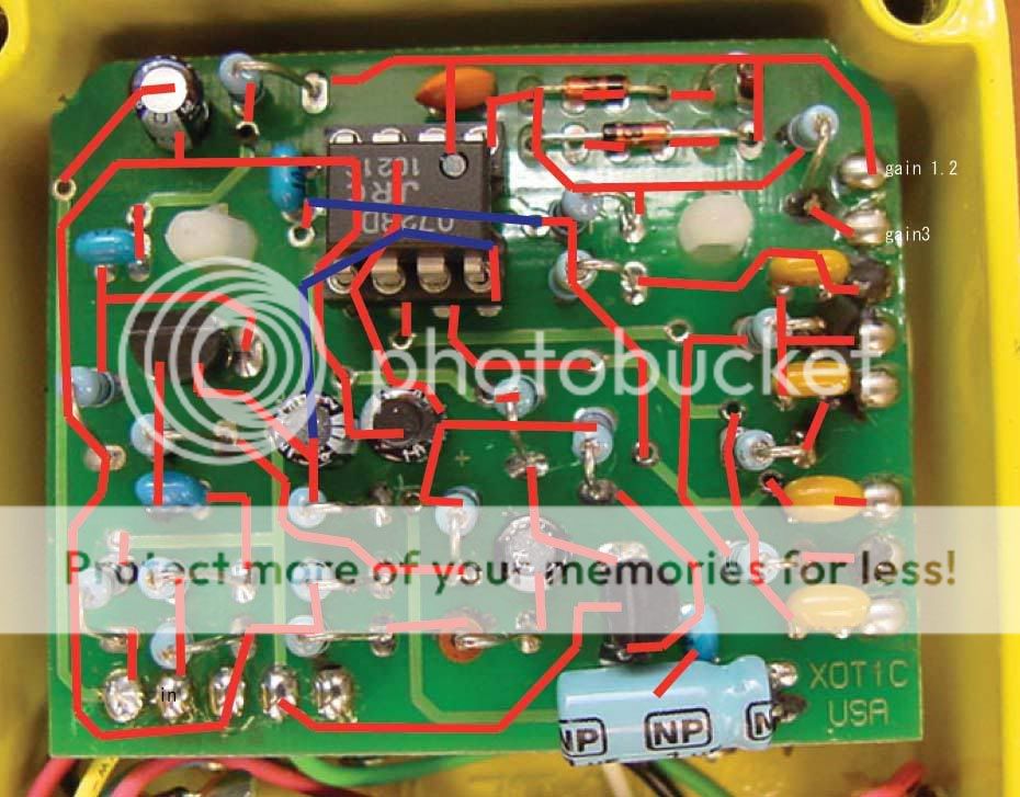
First. I copied the circuit printed on back side to top one.
https://i255.photobucket.com/albums/hh1 ... _84/AC.jpg
and traced that with ts-808 schematic.I've heard AC Booster is similar to TS-808
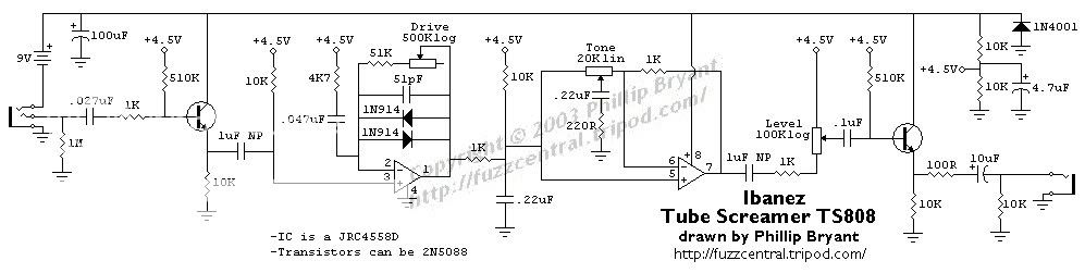
tone,gain part and some values are different but almost all the circuit is the same.
and I found a small mistake on wiring photo.
I think Output could be input.
thanks.
ranmusic84
First. I copied the circuit printed on back side to top one.
https://i255.photobucket.com/albums/hh1 ... _84/AC.jpg
and traced that with ts-808 schematic.I've heard AC Booster is similar to TS-808
tone,gain part and some values are different but almost all the circuit is the same.
and I found a small mistake on wiring photo.
I think Output could be input.
thanks.
ranmusic84
Information
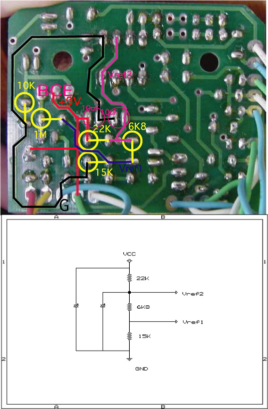
Hello, everybody
I think about Vref1 and Vref2 in this way.
If there is a mistake, please teach it.
I think about Vref1 and Vref2 in this way.
If there is a mistake, please teach it.
Information
- Posts: 5
- Joined: 07 Feb 2008, 11:03
hello! Mr. Gori and Mr. JHS!
thanks for pointing my mistakes!
i've fixed the schematic again.
thanks for pointing my mistakes!
i've fixed the schematic again.
Is there any differences on main signal circuit from original one?The bias supply is correct. The caps are 10uF and Vref1 is only used for biasing the input trannie.
JHS
Information
- Posts: 5
- Joined: 07 Feb 2008, 11:03
i'm really sorry for my mistakes.
Mr.gori told them and i've fixed them.
-add 10uF in bias circuit
-change emitter of output transistor to GND
Mr.gori told them and i've fixed them.
-add 10uF in bias circuit
-change emitter of output transistor to GND