freedreamer wrote:oh great work dude ...
but how have you removed goop?
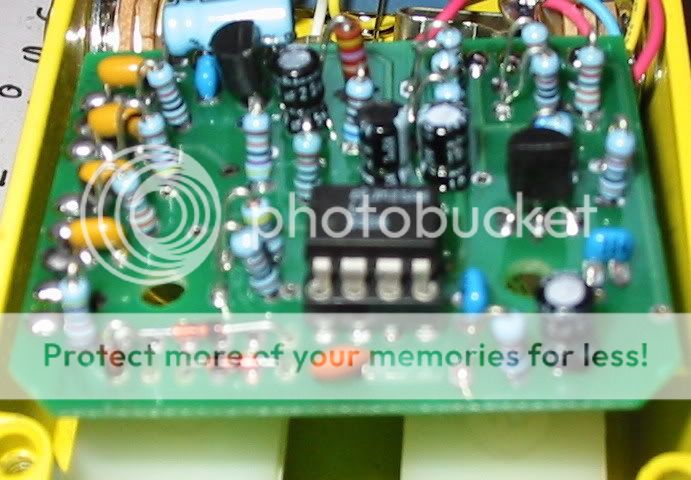
Thanks. An X-acto knife, a pair of needle nose pliers and a pair of eybrow tweezers. The goop wasn't a hard epoxy. It was almost like a rubberized conformal coating. Once I got an edge started I just carefully peeled back the rest. Things I noticed...
1) IC and tranny numbers removed before coating.
2) One lone carbon comp resistor for the necessary mojo.
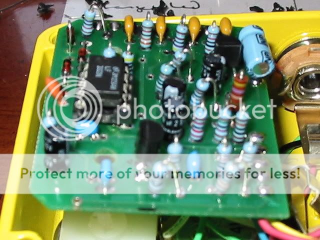
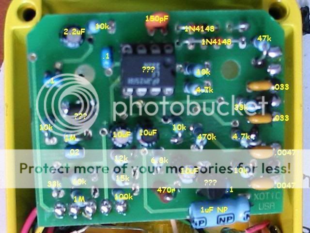
Well I picked up a used AC Booster yesterday and got to work on it. The goop is not nearly as bad as I thougth it would be but it will be slow going. I have changed a couple of things so far...
1) Socketed the IC and went with a LF353N for now.
2) Changed from symetrical to asymetrical clipping.
These two changes worked for me. The pedal is a little more open and less boxey to my ears. I wish I had a second one so I could do a side by side. I'll post follow ups regarding the de-gooping.
@Rotagilla
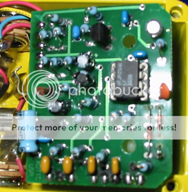
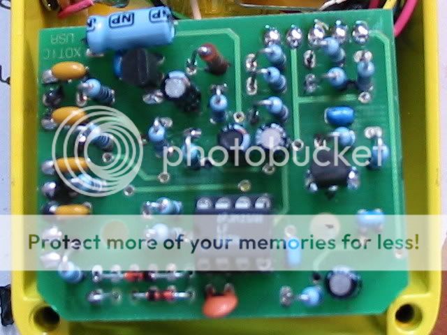
How´s about a photo of the solder/track side ?
analogguru
There´s a sucker born every minute - and too many of them end up in the bootweak pedal biz.
Still there are some values missing there like the values for the bias voltage divider resistors for the input buffer etc which is not clear yet. Perhaps Rotagila can add in the the missing bits.
A clone PCB layout could be nice also if someone got the time in the future
JHS wrote:It's a std. BIAS-devider with an additional 3V tap (lower BIAS-R is spiltted into 2 parts).
JHS
I understand what you are saying. Still, I´m a sucker for getting it 100% correct and not just a similar result. I can spot resistors which are 33k. 15k, 12k and 6.8k which I guess are involved but cannot see the exact respective connections. Perhaps if Rota chimes in everything and get it right.
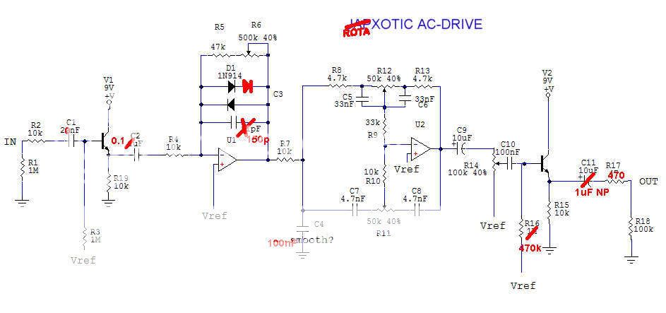
I have tried to correct some other obvious errors in the previous "guessing" schematic traced from the japanese clone looking at rota´s pics. The clipping is now corrected to asymetric (if that was not a mod made by Rota? )
The asymetrical clipping was done by me. I suspect the RC Booster board is the same with the addition of more diodes (maybe I'll keep an eye out for a cheap one). Let me see what I can do about better pics, things have been crazy lately.
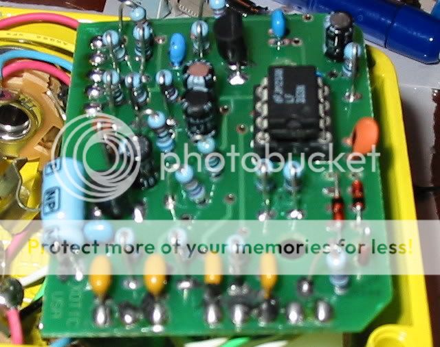
Schematic is still incorrect:
R5(47k) and R6 (poti 500k) have to be exchanged in place
R16 (470k on base of output-buffer) connects to Vref and not to 3V
C11, output cap is polarized
coupling cap C9 is 1µF non-polarized.
in the newly shown bias-divider the 6k6 is in reality 6k8
In the labelled picture the 12k seems to be in reality 22k
analogguru
There´s a sucker born every minute - and too many of them end up in the bootweak pedal biz.


That's nice work Rota, I look forward to seeing the full reverse