Anyway, I have a 10n cap in C10 position (schematic), but it looks like I have C9 (schematic) incorrect. It should be a 10uF Electrolytic. Maybe that's what you were saying all along.
Fulltone - OCD [traced]
I think where I'm getting confused is the schematic and layout numbers don't match. C10 on MarkM's board is C9 on the schematic, and C10 on the schematic is C9 on MarkM's board. Correct me if I'm wrong.
Anyway, I have a 10n cap in C10 position (schematic), but it looks like I have C9 (schematic) incorrect. It should be a 10uF Electrolytic. Maybe that's what you were saying all along.
Anyway, I have a 10n cap in C10 position (schematic), but it looks like I have C9 (schematic) incorrect. It should be a 10uF Electrolytic. Maybe that's what you were saying all along.
-
modman

- a d m i n
Information
- Posts: 4897
- Joined: 19 Jun 2007, 16:57
- Has thanked: 4411 times
- Been thanked: 2139 times
Never ever build from a layout that isn't accompanied by a (correct) schematic. Start from a verified schematic then put a layout you want to use next to it. It wouldn't be the first MarkM layout that takes some liberties it doesn't mention...
Please, support freestompboxes.org on Patreon for just 1 pcb per year! Or donate directly through PayPal
Good advice! I had made the PCB a long time ago and thought I would just finish the build. Lesson learned!modman wrote:Never ever build from a layout that isn't accompanied by a (correct) schematic. Start from a verified schematic then put a layout you want to use next to it. It wouldn't be the first MarkM layout that takes some liberties it doesn't mention...
Seems a few people around here have had success with the same board. They probably read the schematic though.
i built the ocd based on the vero layout.
http://i50.tinypic.com/334i69f.png
all i'm getting is a fuzz like sound.
when the drive pot is all the way down it's kind of gated and really fuzzy when i hit the strings.
almost like my woolly mammoth with the pinch control all the way down to have that gated starving effect.
i tried different 2N7000s as i ordered a bunch. i also tried turned them around 180 degrees. still the same.
the pedal has almost zero dynamic range.
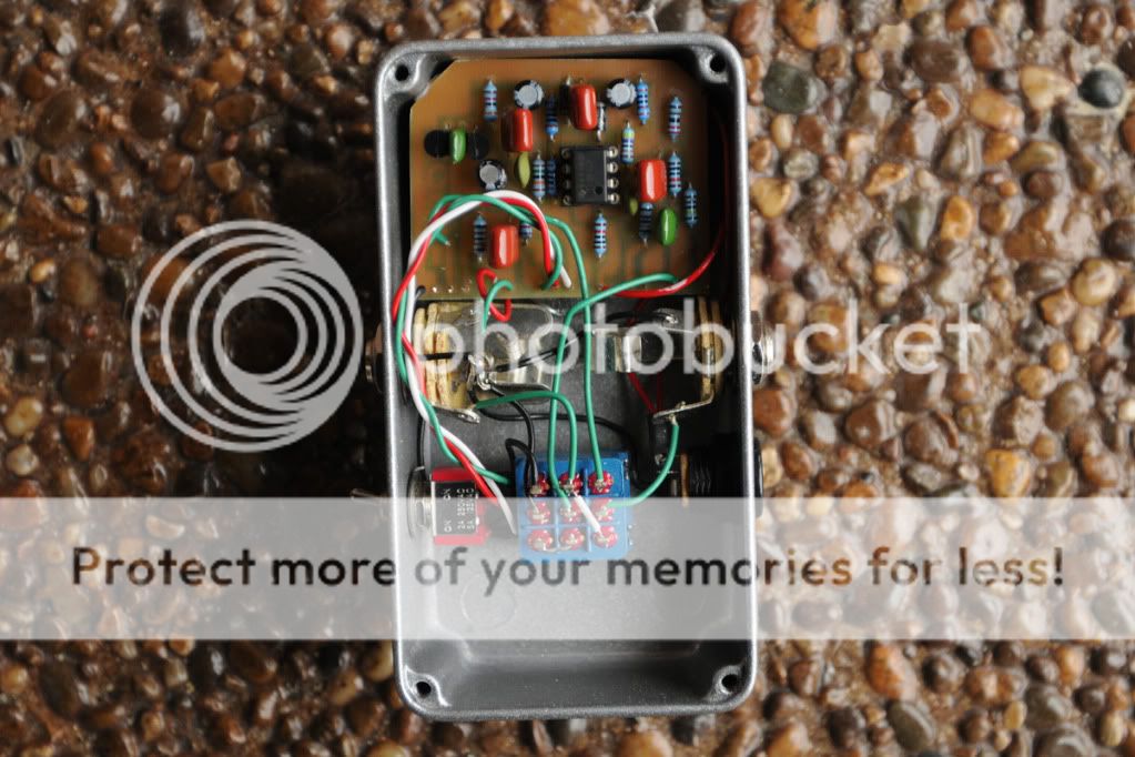
here's a pic of component side of the vero board:
http://i46.tinypic.com/23igscm.jpg
http://i50.tinypic.com/334i69f.png
all i'm getting is a fuzz like sound.
when the drive pot is all the way down it's kind of gated and really fuzzy when i hit the strings.
almost like my woolly mammoth with the pinch control all the way down to have that gated starving effect.
i tried different 2N7000s as i ordered a bunch. i also tried turned them around 180 degrees. still the same.
the pedal has almost zero dynamic range.
here's a pic of component side of the vero board:
http://i46.tinypic.com/23igscm.jpg
-
caspercody

- Resistor Ronker
You could take the 2N7000's completely out, and it should still work. Might want to build an audio probe, and work your way thru the circuit. When I build a pedal that is not working right, this is what I do.
In fact when I did build this pedal I did have a issue of it fizzing out. I replaced a bad electro cap, and now it works. You can also remove the diode, and try it without.
In fact when I did build this pedal I did have a issue of it fizzing out. I replaced a bad electro cap, and now it works. You can also remove the diode, and try it without.
-
madbean
Information
Without the diode you will still get pretty nice clipping. The diode itself kinda softens the transition to clipping, but it also adds some grittiness I found. I've experimented quite a bit with 2n7000 tied to Vb in other circuits, and I always preferred it without the 1n34a.
Actually, looking at Mark's layout the transistors are wrong. Drain and Gate should be connected, not Gate and Source. Flip them around....Source should be the free pin.
Actually, looking at Mark's layout the transistors are wrong. Drain and Gate should be connected, not Gate and Source. Flip them around....Source should be the free pin.
-
madbean
Information
Also, if you are using the GE diode, the cathode (band) should point towards the source pin. You can use a diode on each tranny, or just one, or none.
-
culturejam

- Old Solderhand
Information
I actually like the MosFET-only clipping sound as well.madbean wrote:Without the diode you will still get pretty nice clipping. The diode itself kinda softens the transition to clipping, but it also adds some grittiness I found. I've experimented quite a bit with 2n7000 tied to Vb in other circuits, and I always preferred it without the 1n34a.
Are you serious? I didn't even catch that. I'll have to take another look at the schematic and try flipping them. Thanks for the info. I'm never building a layout without a match schematic again!madbean wrote:Actually, looking at Mark's layout the transistors are wrong. Drain and Gate should be connected, not Gate and Source. Flip them around....Source should be the free pin.
-
sevinisthenumber

- Cap Cooler
please be gentle....
I cant find how to make a version 2?
ANyone lead me the right way/layout/etc...
Thanks
I cant find how to make a version 2?
ANyone lead me the right way/layout/etc...
Thanks
"The man who says he knows everything will never know the truth"
C.S. Lewis
C.S. Lewis
Hey good people,
So I am putting this guy together based on this:

I don't see an output from the board? Am I blind? Didn't even notice till I was done populating the board and wiring up
Would it be Vol lug 2, since that has nothing attached to it? I wired it that way, cuz i didn't know what else to do
I'm not getting an effect signal as it is now And by reading this thread, I know I wired my SPDT wrong
Thanks for any help!
So I am putting this guy together based on this:
I don't see an output from the board? Am I blind? Didn't even notice till I was done populating the board and wiring up
Would it be Vol lug 2, since that has nothing attached to it? I wired it that way, cuz i didn't know what else to do
I'm not getting an effect signal as it is now
Thanks for any help!
-
Greg

- Old Solderhand
Yes, the output is from the centre lug of the Volume pot as per schematic.kungpow wrote:Hey good people,
So I am putting this guy together based on this:
I don't see an output from the board? Am I blind? Didn't even notice till I was done populating the board and wiring up
Would it be Vol lug 2, since that has nothing attached to it? I wired it that way, cuz i didn't know what else to do
I'm not getting an effect signal as it is now
Thanks for any help!
culturejam wrote: We are equal opportunity exposure artists.
-
Greg
- Old Solderhand
That's marked on the layout..useme2305 wrote:kungpow, since you obviously didn't even take a look at the attached wiring scheme:
don't forget to ground lug one of the vol and tone pots.
culturejam wrote: We are equal opportunity exposure artists.
-
Dr Tony Balls

- Diode Debunker
I built from that layout and can confirm it.
-
B_of_H
- Breadboard Brother
I've been gigging with a build from the above layout for close to a year now. I did play around with the values of c10 and c11. I'm not sure what I ended up with but the pedal is a lot brighter than it was with the stock values. I use it with the tone at about 11:00 now instead of 2:00 or higher when I first built it stock.
Yay! 
Thanks for the responses. Got it to work; sounds good, not quite as much gain as I would've expected when dimed. A few questions remain, however:
1)
2) I know the HP/LP switch is a high/low pass filter. Seems when I put it in HP, I get a noticeable Vol boost. As I interpret the layout, I have lug 3 of Vol pot to lug 1 of S1, and then the board's "S1" to lug 2 of my SPDT. Then I put a small jumper btwn lugs 2 & 3 of that. Is this normal/others experience? Am I wiring this right?
3) Lug 3 of Drive pot is empty. Should it be grounded, or o/w attached to something?
Thanks!
Thanks for the responses. Got it to work; sounds good, not quite as much gain as I would've expected when dimed. A few questions remain, however:
1)
I wired them together. Is that grounded?Greg_G wrote:useme2305 wrote:don't forget to ground lug one of the vol and tone pots.
2) I know the HP/LP switch is a high/low pass filter. Seems when I put it in HP, I get a noticeable Vol boost. As I interpret the layout, I have lug 3 of Vol pot to lug 1 of S1, and then the board's "S1" to lug 2 of my SPDT. Then I put a small jumper btwn lugs 2 & 3 of that. Is this normal/others experience? Am I wiring this right?
3) Lug 3 of Drive pot is empty. Should it be grounded, or o/w attached to something?
Thanks!