
Do you have any of those PCBs that you said you made a layout for, that aren't etchable?
I'd totally build one if I could get the parts going for it. There's a spot on my pedalboard waiting for a bit/sample reduction pedal. I'd sooner something DIY than the big WMD one.
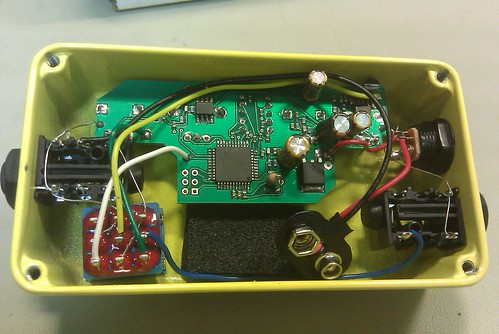
WMD Geiger Counter - [gut shots]
-
oldgravity

- Solder Soldier
Information
- Posts: 161
- Joined: 25 Mar 2009, 06:37
- Location: New Orleans, LA
I use them for commercial stuff, and I don't have many, so for now I'm not planning to sell any. The Tonepad one is workable though. The only major thing it needs added is a 15p cap from the crystal to ground. The weird thing about it is that you'd have to solder the EEPROM socket on the copper side - I don't know why they did that, as most people are not going to use an SMD EEPROM. 
I suppose if enough people were into it I could sell some boards like I did with the tap tempo trem, gristleizer, etc. but at the moment I'm not sure there'd be enough interest (i.e. I'd have to charge more per board than people would want to pay).
Small Bear has the FV-1 and necessary crystal.
I suppose if enough people were into it I could sell some boards like I did with the tap tempo trem, gristleizer, etc. but at the moment I'm not sure there'd be enough interest (i.e. I'd have to charge more per board than people would want to pay).
Small Bear has the FV-1 and necessary crystal.
So in order to build this, I would need to etch the tonepad layout, buy all the parts (including an SMD FV-1), and that's it?
How would it be reprogrammed? I've got a USBtinyISP programmer. Would that work?
Honestly, I think there's a decent amount of interest in this. On the Harmony Central forum, there are people lining up, to wait in line, for a similar thing.
There was a thread recently, but it got lost as they migrated the forum to a new version (looks terrible!)
Point is, this guy was making a simple 2knob (reduction and blend) sample rate reducer, and people were all over it, and he was only making one at a time.
I think a straight, 3knob crusher pedal, that would fit into a 125b would be a hot product.
-
oldgravity
- Solder Soldier
Information
- Posts: 161
- Joined: 25 Mar 2009, 06:37
- Location: New Orleans, LA
You program the code to an EEPROM chip, so you'll need an EEPROM programmer. I don't think the programmer you have will do it. I program my chips with the FV-1 development board, but standalone EEPROM programmers are available for not too much money. I could also sell you a programmed chip if you want.
-
oldgravity
- Solder Soldier
Information
- Posts: 161
- Joined: 25 Mar 2009, 06:37
- Location: New Orleans, LA
Don't know anything about Arduino, sorry. I'd probably do sample rate, bit reduction, then an effect/clean mix. However, I am curious, after your last couple posts: are you going to want to sell these? I want to support DIY, but I'm not really cool with people using my stuff for commercial use, you know?
Don't know what gave you that impression. I'd be lucky to build one for my own personal use.
I only mention the viability for selling them, as a selling point for you to make PCBs available for it (so it would be easier for me to build one).
I only mention the viability for selling them, as a selling point for you to make PCBs available for it (so it would be easier for me to build one).
-
Space Jm
- Breadboard Brother
Ready for some informations ? 
I did not check deeply but, just to start , on the civilian version; the µC seems to be a 44 pins QFP , rright ?
http://farm5.static.flickr.com/4036/434 ... af3bb2.jpg
So here the model...
Freescale
http://www.freescale.com/files/microcon ... 08GP32.pdf
MC68HC908GP32

I did not check deeply but, just to start , on the civilian version; the µC seems to be a 44 pins QFP , rright ?
http://farm5.static.flickr.com/4036/434 ... af3bb2.jpg
So here the model...
Freescale
http://www.freescale.com/files/microcon ... 08GP32.pdf
MC68HC908GP32
Together we stand, divided we fall
Just wanted to try and revive this thread. This is a cool project I'd like to see finished. I built my first effect with a chip (tap tempo trem) and its making my brain work on all the possibilities with micro controllers. Besides, the tap trem and something like the wmd geiger counter would sound so sick together.
-
devastator

- Cap Cooler
have you gone futher with this project ? seems really nice ! (espcially if it's not a clone but a original design)oldgravity wrote:Yo guys. I have a proposition for you. I have become decent at programming the FV-1 DSP chip. This kind of effect isn't that difficult with this sort of architecture. I am up to do some coding. This would not be a clone of the Geiger Counter, but it would be the only wavefolding digital distortion DIY project I'm aware of. In terms of building the actual hardware, you could build Tonepad's FV-1 reverb board and just load in the code I post here.
So, first let me know if you're interested in building this. I enjoy doing these kinds of projects and would like having this sort of effect myself, but I'm fairly busy at the moment and can't spend the time if nobody cares.
Second, if there are a few people into it, give me some thoughts on what features you'd want implemented. The FV-1 is limited to 3 pots, plus a fourth with a little hacking, but you can wrap it with analog stuff to add some pots, i.e. mix, volume, input gain can be done in analog, which leaves 3 or 4 pots to do the digital stuff. It's possible to have either a 4-position rotary and a toggle, an 8-position rotary, or 3 toggles. Stereo IO but one in and out gets used up by the "fourth pot trick".
Let me know what you think and maybe we can make this happen. I'm not going to straight out clone their wavetables or anything, I don't like straight cloning anyone's work. But we can make a cool project together that gets some similar sounds.
otherwise, the distortions is produced by the µC or an analog circuit ?
-
Space Jm
- Breadboard Brother
So the guitar feed an AOP with a drive, then it goes to an AD/DC, then into the µC.
Out of the µC it goes to an DC/AC then out.
The distortion is made by a combinaison of the input guitar signal in Digital mode, and the wave forms inside the µC.
I guess it works like a synthemonger, or pulsemonger : an oscillator(waveform) is combine with the guitar signal and creates the sound...but I do not know how ?
Together we stand, divided we fall
-
devastator
- Cap Cooler
I didn't know the synthmonger , fuzzmonger ect.... Really cool stuff !
I just have to find more imformations about their circuits now
-
Space Jm
- Breadboard Brother
To be honnest, Geiger Counter is really a BIG CHEESE, I do not think it is possible to DIY.
It needs a huge µC QFN, not possible to be soldered it with an iron, only with a reflow oven and a dynamic T° curve.
The code inside should be enormous also.
It should be possible to do a small stuff...with 10 curves maxi...
It needs a huge µC QFN, not possible to be soldered it with an iron, only with a reflow oven and a dynamic T° curve.
The code inside should be enormous also.
It should be possible to do a small stuff...with 10 curves maxi...
Together we stand, divided we fall
-
devastator
- Cap Cooler
Acutally cloning isn't what I'm looking for. I just want to understand the concept and general layout.
I started getting into µC and it's always good to look at other's work to understand things.
I started getting into µC and it's always good to look at other's work to understand things.