I got one from Futurlec.CodeMonk wrote:Got all the files for building one, but....sources for the metal can 741?
Crowther Audio - Hot Cake Overdrive [traced]
-
culturejam

- Old Solderhand
Information

does anyone have a diagram including the guitar/bass and normal/bluesberry switching options?
-
bajaman

- Old Solderhand
Information
- Posts: 4549
- Joined: 26 Jun 2007, 21:18
- Location: New Brighton, Christchurch, NZ
- Has thanked: 596 times
- Been thanked: 2061 times
ask PEC - he is a member here 
be kind to all animals - especially human beings
I suppose I could crack into my hotcake and have a look at what the switching circuit is doing, just thought someone might have traced it already,
I'm building a couple "hotcake/prunesncustard" in one pedals and thought it'd be cool to have all the switching options on the front of the pedal
I'm building a couple "hotcake/prunesncustard" in one pedals and thought it'd be cool to have all the switching options on the front of the pedal
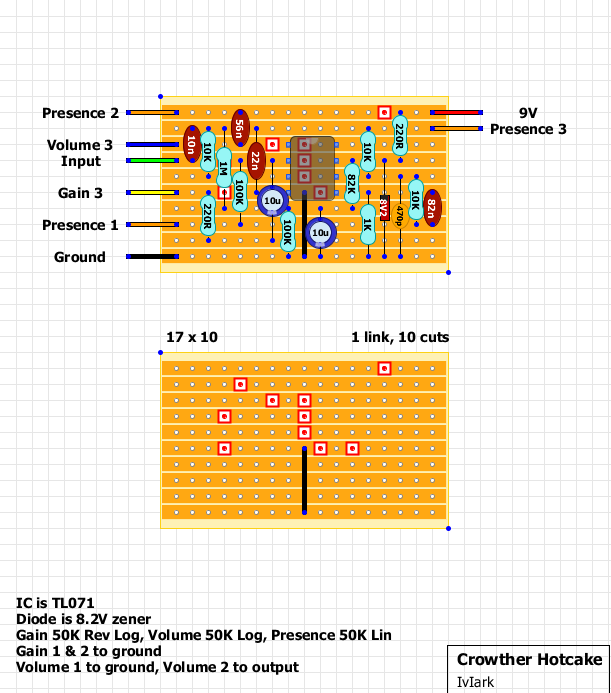
Hey everyone, so I put together the pedal based on the stripboard at http://www.sabrotone.com/wp-content/upl ... joCake.gif
Here's the issue. When the pedal is engaged it takes a second or two for the effect to come through. I checked the DC voltage across the output jack and realized that when disengaged it is 4.3V and when engaged, 0.3V.
Can anyone please tell me what the issue is with the stripboard layout? I'm assuming there's an error. THANKS IN ADVANCE!!!
-
mysticwhiskey

- Solder Soldier
There's not too much to go on in your post, so I guess standard debugging steps should apply here such as:
* Check all electrolytic caps are oriented correctly
* Measure the voltage for all active pins of the opamp (pins 2,3, 4, 6 and 7)
* Measure voltage of battery (or power supply)
* Double check that all 11 cuts have been made in the vero, and that the 2 jumpers are in place
* Check for solder bridges between the vero tracks, or any accidental copper bits from the cuts that may be bridging vero tracks
* Are all resistor values correct
* Do all pots work as expected?
You may have better luck obtaining help if you post clear hi-res photos of your board (both component and solder side), and also include pics of the wiring for the pots, DPDT footswitch and the input/output jacks.
One thing I noticed is that the vero layout doesn't have a DC blocking cap between the volume pot's pin 3 and the presence pot's pin 2 - there was a discussion about this cap on the previous page. You'd probably want to put this in to block any DC coming out of the pedal, and also to prevent DC across the volume pot This would be as simple as replacing the wire connection between the volume and presence pots with a 56nF cap (the value of 56nF is taken from analogguru's schematic at http://analogguru.an.ohost.de/193/schem ... e-2003.gif)
-
lukatosh

- Solder Soldier
hello!
well, tonight i've populated the PCB and hear how it sounds... But, i have some issues i think..
For the gain... I used a c50k but it was too sensitive so i change it to a B10k... but i noticed that I dont have much gain like some hotcake youtube videos... with the gain pot at 12 it sounds like a clean booster...
also, at higher gain settins the pedal get too much dark and it sound horrible!.... it gets a fuzz sound... and you can hear that the gain pot acts like sort of filter...
i've build it using this layout:
viewtopic.php?f=13&t=11809#p176545
What can i do to solve this problems? ...
Thanks for your help!,
please... excuse my poor english!, i'm writing from chile!
Saludos!
Thinking of doing a build using this: http://www.sabrotone.com/?p=1352 layout, based on the schematic attached.
wanna use the LM741 op amp so from what i'm reading i should throw a 220k resister in there. my question is, where on the layout would i put that? between leg 2 of the op amp annnnnd???? the second rail from the bottom? where R2, R3, R4 and C2 (based on the vero layout numbers)connect?
wanna use the LM741 op amp so from what i'm reading i should throw a 220k resister in there. my question is, where on the layout would i put that? between leg 2 of the op amp annnnnd???? the second rail from the bottom? where R2, R3, R4 and C2 (based on the vero layout numbers)connect?
- Attachments
-
Thanks for confirming that for me. next question, a little confused about the off-board wiring. i think the vero-layout gives me everything i need for the pots, but i'm a little hazy about how i should wire the dpdt switch. anyone wanna point me in the right direction?
-
rocklander

- Old Solderhand
Information
- Posts: 2726
- Joined: 18 Apr 2008, 11:33
- my favorite amplifier: my jansen bassman 50
- Completed builds: rebote 2.5; supreaux; odie; heartthrob tremolo; ross phaser; dr. boogey; thor; baja black toast; slow gear attack, rebote, tri-vibe, small clone, little angel, magnus modulus, echo base, hex fuzz, big muff, 22/7.
- Location: Rotorua, New Zealand
- Has thanked: 1406 times
- Been thanked: 231 times
- Contact:
https://www.freestompboxes.org/viewtopic ... dt#p167177jeremysbrown wrote: i'm a little hazy about how i should wire the dpdt switch. anyone wanna point me in the right direction?
world's greatest tautologist ...in the world
Ronsonic wrote:...the lower the stakes the more vicious the combat.
atreidesheir wrote:He should be punched in the vagina.
hmmmm, yea, i have actually done a fair bit of searching. that link is for a 3pdt switch. i plan to use a dpdt as per the schematic/layout i'm using. just trying to blend the small bit of info as far as the vero- layout explains the switch wiring with what i've read in other places. if i were to go specifically by the vero, i'd hook up just the first second and third leads of the switch, which makes me wonder why i'm using a dpdt at all. anyways, i'm sure it's a simple solution, just don't wanna screw it up.
-
rocklander
- Old Solderhand
Information
- Posts: 2726
- Joined: 18 Apr 2008, 11:33
- my favorite amplifier: my jansen bassman 50
- Completed builds: rebote 2.5; supreaux; odie; heartthrob tremolo; ross phaser; dr. boogey; thor; baja black toast; slow gear attack, rebote, tri-vibe, small clone, little angel, magnus modulus, echo base, hex fuzz, big muff, 22/7.
- Location: Rotorua, New Zealand
- Has thanked: 1406 times
- Been thanked: 231 times
- Contact:
dpdt is the same, but just omit the LED wiring
world's greatest tautologist ...in the world
Ronsonic wrote:...the lower the stakes the more vicious the combat.
atreidesheir wrote:He should be punched in the vagina.
I thought there used to be a layout/schematic for this with TB 3PDT switching? I already have a hotcake so not too worried about the buffer being off when I turn the pedal off, as I',m building a Hotcake and PrunesnCustard into one box

Information
Is it public what does the bluesberry toggle change?
I can not find it anywhere...
I can not find it anywhere...

Information
I made this pedal from this layout:
I made it true bypass.
It works well but oscillates when engaged. Does not oscillate in bypass. How should I start looking for a solution?
Thanks
I made it true bypass.
It works well but oscillates when engaged. Does not oscillate in bypass. How should I start looking for a solution?
Thanks