alltrax wrote: ↑08 Oct 2020, 08:45 I built this pedal on vero according to this layout :
https://tagboardeffects.blogspot.com/se ... flux+drive
I believe it follows the schematic posted here in the 1st post.
Everything works well and I like it very much, but the output level is low, barely unity volume with level pot full CW.
I tried to bypass the output buffer with my probe thinking the issue could be there but it's the same.
Anybody built it, any idea ?
Thanks
Mesa Flux Drive (vero) low output
-
The G

- Grease Monkey

-
The G
- Grease Monkey
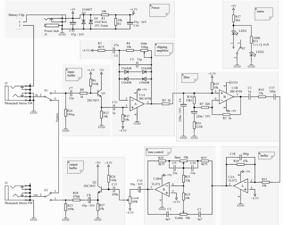
Audio probe the signal along its path (see test points in the image):
1. Input buffer output, the signal should be identical to your clean guitar signal.
2. Set the Gain pot to the max and the signal here should be quite distorted, depending on your guitar pickups output.
3. Filtered signal
4. This ia actually an inverting x4.7 amplifer (not much of a buffer with 10k at the input), so the signal should be louder than at 3.
5. Tone circuit output, you can test here that tone controls work.
6. Pedal output, set the Level pot to the max and it should be identical to 5.
-
deltafred

- Opamp Operator
As long as the layout is verified then low output is probably caused by one (or more) of the following -
Missed or incomplete cut on the vero. - Check for all cuts present. If you used a drill bit make sure that you haven't left a tiny bit of copper at one side of the cut.
Solder bridge between tracks. - Visually check for solder bridges. you should be able to run the tip of a small flat bladed screwdriver between the tracks. Doing this clears out any solder blobs, excess flux, and general debris from between them.
Dry (cold) solder joint. - If you are using the modern lead free solder (I hate that stuff) it can be quite difficult to get good joints. Remake any that you feel might not be making proper contact.
Wrong value component fitted. - It is quite easy to get a resistor value a decade out.
Polarised component (electrolytic capacitor or semiconductor) fitted incorrectly.
Faulty component - These don't usually show any visible signs unless they have passed too much current and overheated.
Follow the testing procedure outlined by The G to identify which stage the fault is in then concentrate your search on that stage.
Once you get it working correctly report back here what the fault was.
Politics is the art of so plucking the goose as to obtain the most feathers with the least squawking. - R.G. 2011
Jeez, she's an ugly bastard, she makes my socks hurt. I hope it's no ones missus here. - Ice-9 2012
Jeez, she's an ugly bastard, she makes my socks hurt. I hope it's no ones missus here. - Ice-9 2012
-
alltrax

- Breadboard Brother
Information
Ok, so the 1st thing I did is to check all what deltafred suggested. Actually I already did it 3 or 4 times, but this time with fresh eyes, under a magnifying light for the trace side.
I didn't see anything wrong, trace cuts are good (I use a 3.5mm drill bit and always check and remove the small copper that's sometime left between the traces before starting soldering), no solder bridge. I reflowed a couple solder joints that were not shiny. On the other side of the board I checked every component placement and value, everything seems correct.
Now the audio probe :
1- Ok, signal identical to clean signal
2- Yes, distorted signal, and very high output actually
3- About the same than 2
4- The problem could be between 3 and 4, here I loose a lot of output comparing to 3
5- Almost identical to 4, with a little bit more output, but not significative
6- identical to 5
I'll focus between 3 and 4 then
Last edited by alltrax on 11 Oct 2020, 18:28, edited 1 time in total.
-
Intripped

- Cap Cooler
IMO the forum should have some "sticky" posts like this in the troubleshooting sectiondeltafred wrote: ↑10 Oct 2020, 13:42 As long as the layout is verified then low output is probably caused by one (or more) of the following -
Missed or incomplete cut on the vero. - Check for all cuts present. If you used a drill bit make sure that you haven't left a tiny bit of copper at one side of the cut.
Solder bridge between tracks. - Visually check for solder bridges. you should be able to run the tip of a small flat bladed screwdriver between the tracks. Doing this clears out any solder blobs, excess flux, and general debris from between them.
Dry (cold) solder joint. - If you are using the modern lead free solder (I hate that stuff) it can be quite difficult to get good joints. Remake any that you feel might not be making proper contact.
Wrong value component fitted. - It is quite easy to get a resistor value a decade out.
Polarised component (electrolytic capacitor or semiconductor) fitted incorrectly.
Faulty component - These don't usually show any visible signs unless they have passed too much current and overheated.
Follow the testing procedure outlined by The G to identify which stage the fault is in then concentrate your search on that stage.
Once you get it working correctly report back here what the fault was.
-
deltafred
- Opamp Operator
Just a WAG but did you remember to put the link under the TL072?
Not having the +4.5v bias on pin 3 could cause the opamp to do strange things.
Not having the +4.5v bias on pin 3 could cause the opamp to do strange things.
Politics is the art of so plucking the goose as to obtain the most feathers with the least squawking. - R.G. 2011
Jeez, she's an ugly bastard, she makes my socks hurt. I hope it's no ones missus here. - Ice-9 2012
Jeez, she's an ugly bastard, she makes my socks hurt. I hope it's no ones missus here. - Ice-9 2012
-
alltrax
- Breadboard Brother
Information
-
The G
- Grease Monkey
Intripped wrote: ↑11 Oct 2020, 18:21IMO the forum should have some "sticky" posts like this in the troubleshooting sectiondeltafred wrote: ↑10 Oct 2020, 13:42 As long as the layout is verified then low output is probably caused by one (or more) of the following -
Missed or incomplete cut on the vero. - Check for all cuts present. If you used a drill bit make sure that you haven't left a tiny bit of copper at one side of the cut.
Solder bridge between tracks. - Visually check for solder bridges. you should be able to run the tip of a small flat bladed screwdriver between the tracks. Doing this clears out any solder blobs, excess flux, and general debris from between them.
Dry (cold) solder joint. - If you are using the modern lead free solder (I hate that stuff) it can be quite difficult to get good joints. Remake any that you feel might not be making proper contact.
Wrong value component fitted. - It is quite easy to get a resistor value a decade out.
Polarised component (electrolytic capacitor or semiconductor) fitted incorrectly.
Faulty component - These don't usually show any visible signs unless they have passed too much current and overheated.
Follow the testing procedure outlined by The G to identify which stage the fault is in then concentrate your search on that stage.
Once you get it working correctly report back here what the fault was.
Very good idea, there is now a new "Debugging 101" subforum.
It is intended to house all good general advice for debugging, so expert advice would be very much appreciated.
Also, if someone notices a valuable piece of information that belongs there, please let us know.
-
alltrax
- Breadboard Brother
Information
Ok it works 
Wrong resistor value....4k7 instead of 47k (R18 between IC2 pins 1 and 2). I previously checked with color codes and both are almost identical. Knowing now that the problem was around IC2 first opamp, I checked with my DMM and bingo !
A lot of output volume now (I'll replace the pot with an audio taper one, at 10 O'clock it's almost full volume with the lin).
Thank you guys for the help !
And if I may, what would it take to have a little bit more gain out of this circuit ?
Thanks
-
deltafred
- Opamp Operator
If all the links, cuts, solder joints and components look ok then it's time to start checking components.
/rant
I have no idea why there are 2 caps and 2 resistors in series (C1, R10, C17, R11). This indicates to me that whoever "designed" this didn't really know what they were doing and probably cobbled together stages from other circuits.
The combined resistance of the 2 series resistors R1 + R17 is 33k + 10k = 43k so why not use a single resistor around that value.
The combined capacitance of 2 capacitors in series is a bit more complicated but when they are a couple of orders of magnitude difference in value you could replace the 10uF capacitor with a link and you wouldn't hear the difference.
rant/
Back to debugging. Try the easy things first.
If you socketed the ICs (I prefer to) then try another 072 if you have one or if you don't then swap IC1 and IC2 and see if the fault changes to the clipping amplifier section.
If you didn't socket the ICs then check the resistors and capacitors before you try changing the 072. If you do need to unsolder it I would advise fitting a socket (personal preference).
The gain of an inverting opamp = R feedback (R18) / R input (R1 + R17)*
If R10 or R11 are high resistance or C1 or C17 are open circuit then the gain will be reduced according to the formula above.
You can check the resistance of each without desoldering them because the 2 capacitors will block DC (which ohmmeters use to measure resistance with so non of the other circuitry will affect the readings).
If either C18 is leaky (possible) or R18 is a low value (unlikely) then the gain of the opamp will be lowered accordingly.
I'm not sure how much the internal circuitry of the opamp will affect the reading if you put an ohmmeter across C18/R18. Try it and see what it reads but if it does read less than 47k don't assume that either R18 or C18 is faulty. Unsolder one end of each and check them out of circuit.
*In the middle of the pass band, the lower end is of which is determined by C17 and R10+R11, the high end by C18 and R18.
Hope this helps.
Politics is the art of so plucking the goose as to obtain the most feathers with the least squawking. - R.G. 2011
Jeez, she's an ugly bastard, she makes my socks hurt. I hope it's no ones missus here. - Ice-9 2012
Jeez, she's an ugly bastard, she makes my socks hurt. I hope it's no ones missus here. - Ice-9 2012
-
alltrax
- Breadboard Brother
Information
Thank you Deltafred, your explanations help me to understand how things work.
As mentionned in my previous post, I had a wrong resistor value, R18 was 4k7 instead of 47k so according to the formula it was indeed affecting the gain at this stage.
No I have plenty of output volume with the right R18 value.
So, if I want a bit more gain in the clipping stage, would reducing R3 to let's say 2k be a good idea ?
Thanks
-
deltafred
- Opamp Operator
Glad you got it working, you posted as I was writing my reply.
Yes to increase the gain of the clipping stage reduce R3 but -
R3 and C4 form a filter* so to maintain the same frequency characteristics of the stage you would also need to increase the value of C3 by the same ratio that you decreased R4. (If you halve R3 then double C4.) Use the nearest preferred value. There is no need to get hung up on being too precise as component tolerances aren't that accurate, particularly capacitors.
* The corner frequency f=1/(2 x Pi x R x C) (where R is in ohms and C in farads)
Which for 4.75k and 47nF gives 700Hz (713 actually but with component tolerances there is no need to be that precise.)
Politics is the art of so plucking the goose as to obtain the most feathers with the least squawking. - R.G. 2011
Jeez, she's an ugly bastard, she makes my socks hurt. I hope it's no ones missus here. - Ice-9 2012
Jeez, she's an ugly bastard, she makes my socks hurt. I hope it's no ones missus here. - Ice-9 2012
-
alltrax
- Breadboard Brother
Information
Right, I will socket R3 and C4 and try different combos.
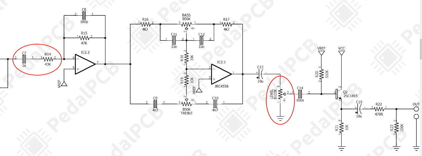
On a side note, I compared this schematic with the one from pedalpcb : WRT your previous remark concerning the resistors and capacitors in serie, on pedalpcb's schem the 100n following the 1µ is omitted, and there is a 43k for 10k + 33k in serie.
One other thing, Level 1 lug is connected to ground instead of Vref.
https://www.pedalpcb.com/docs/GaussDrive.pdf
-
deltafred
- Opamp Operator
That won't make any difference because there is a capacitor before and after it so it will only see AC.
It is not a good idea to have DC on pots in the audio path because they often make a "wooshing" sound as you turn them.
Presets are fine with DC on them because you never usually adjust them when you are using the pedal and some need DC - FET bias adjustment presets.
Politics is the art of so plucking the goose as to obtain the most feathers with the least squawking. - R.G. 2011
Jeez, she's an ugly bastard, she makes my socks hurt. I hope it's no ones missus here. - Ice-9 2012
Jeez, she's an ugly bastard, she makes my socks hurt. I hope it's no ones missus here. - Ice-9 2012