Original effects with schematics, layouts and instructions, freely contributed by members or found in publications. Cannot be used for commercial purposes without the consent of the owners of the copyright.
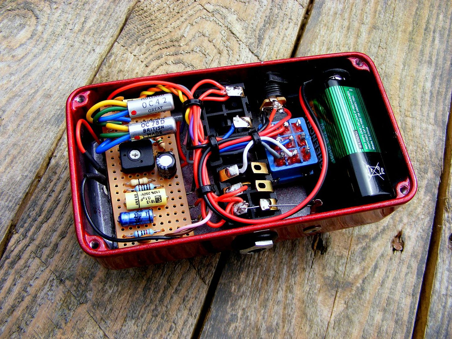
Heres layout for Super Bee - basicly its Vox Tone Bender circuit type with input and output cap changed to 100nF.
Many different types of trannies where used, just use your favourite gain buckets - I like 60-75 hfe for Q1 and 75-105 hfe for Q2, or something like this, theres no magic numbers - always breadboard trannies before soldering and use Your ears
You can move R5 resistor (led pulldown) on switch, as in SB-66 version.
"You've converted me to Cubic thinking. Where do I sign up for the newsletter? I need to learn more about how I can break free from ONEism Death Math." - Soulsonic
atreidesheir wrote:How much advantage is gained by insulating the transitor legs?
The DAM stuff is always nice to examine. Nice work. No Jack Deville, but really nice at the craft.
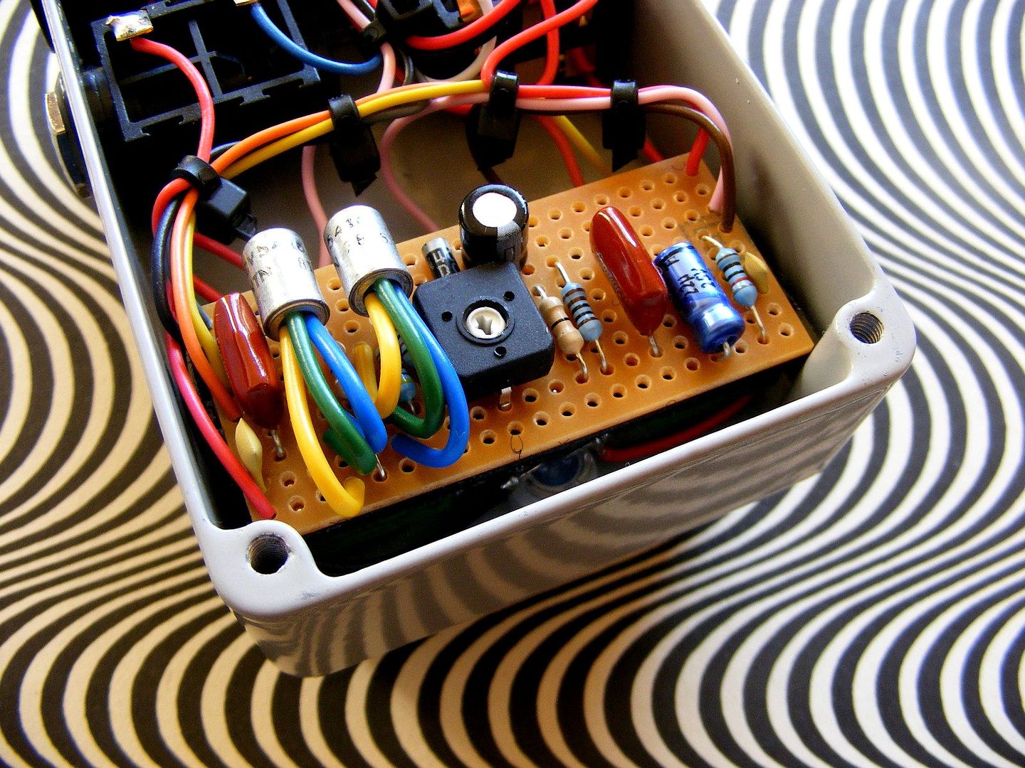
The transistors are germanium types and are sensitive to heat, if you solder them in place with short legs, you run the risk of damaging them from excessive heat, so to get around that, you solder them in with a bit of extra leg length, Insulating the transistor's legs basically stops them from shorting-out, it also helps when identifying which leg is the Base,Emitter, and Collector.....
Genius is not all about 99% perspiration, and 1% inspiration - sometimes the solution is staring you right in the face.-Frequencycentral.
These all look great! Thanks for sharing your layout. When you said to breadboard the transistors first, what's the purpose of doing that? Does it have something to do with adjusting the collector resistors if needed?
I particularly like the idea of using cable-ties to keep all the wiring nice and neat, something that I might start doing with all my future stompbox builds....
Genius is not all about 99% perspiration, and 1% inspiration - sometimes the solution is staring you right in the face.-Frequencycentral.
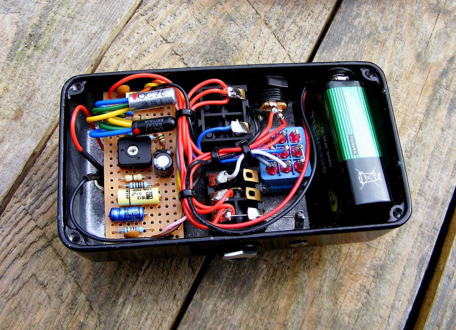
Finished build with OC81. Sounds really great, IMO better than original one
Brighter and little more gainy (used hfe - around 75 for Q1 and 115 or something for Q2). So layout is verified!
bigmufffuzzwizz wrote:These all look great! Thanks for sharing your layout. When you said to breadboard the transistors first, what's the purpose of doing that? Does it have something to do with adjusting the collector resistors if needed?
No. You can try how transistor sounds like before soldering them and choose best sounding pair (if You have some to choose from...). Just pick wich You prefer most with less noise.
You can adjust Q2 volatege using trimmer. Just like sundial in sunfaces.
Sorry to bump an old thread, but having some trouble with the sb-66 layout. First post from a longtime lurker!
I built a Super Bee according to this layout with an added voltage inverter and am not getting any signal with the pedal on (getting sound when bypassed). I'm using an OC71 for Q1 and an OC76 for Q2, using open frame mono jacks and no battery (so I brought a ground wire to the input jack from the top row, also from the level pot and the ground from my inverter board), and have my input jack wired correctly for the inverter (standard negative ground wiring at the DC jack, then the inverter board wires to the Super Bee board and to ground).