Seamoon - Funk Machine [schematic]
-
madbean

Information
This thread just blew my mind. It's a sign of a true engineer that can recall so much detail on something made decades ago. Bravo!
-
greenskull

- Resistor Ronker
Thanks Jerry!!!!! Hope you will join us again soon. 
fuck smooth tone, fuck eric johnson - Seiche
-
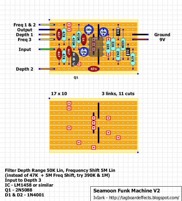
IvIark
- Tube Twister
Information
Vero layout for the etchophobes like me
"If anyone is a 'genius' for putting jacks in such a pedal in the only spot where they could physically fit, then I assume I too am a genius for correctly inserting my legs into my pants this morning." - candletears7 - TGP

It works! Finally my SFM works!
I tried IvIark's layout and works fine, but I have another layout who works with a LM4558, in a few days I will post the results of it.
Thanks IvIark! And many thanks to Rhandy Gaye for the patience!
Max
PD: sorry for my very poor english...
I tried IvIark's layout and works fine, but I have another layout who works with a LM4558, in a few days I will post the results of it.
Thanks IvIark! And many thanks to Rhandy Gaye for the patience!
Max
PD: sorry for my very poor english...
When I'm attacked by Christians, I proudly repond: Your GOD was nailed to the cross, mine has a hammer in his hand, draw your own conclusions... Nergal (Behemoth)

Hi All; first post here. I've read through this thread a bunch of times as well as the other SFM threads here (and elsewhere).
I sooo badly want to get this thing to work, but I also have the "bird sound" that negrosinfe speaks of.
Tried subbing a bunch of resistor values, adding a pot here and there, and even trying to toss in some capacitance. I verified my layout (a few times), but the bird noise persisted when using "V1", "V2", the one showing some mods in circles.
I've only used a 741 like the schematic calls for. Is the 1458 the magic bullet? I presume many have had luck w/ the 741.
The bird noise would disappear throughout the range of adjustment, even in the standard configuration (V1, V2, & V1 w/ mods), and my various diddlings could eliminate it completely, but it was at the expense of getting any real effect from the circuit.
My test rig is a solderless breadboard on an anti static mat/grounded bench, a couple of 10' cables, Squier Bronco w/ single coils and HB, and a Rumble 15 amp.
I've tried (good) battery power, as well as a cheap wall wart and the noise persisted. The cheap wall wart has it's own noise different from what I'm contending with
Anybody have any ideas?
Negrosinfe, could you provide any specifics on your fix?
Dream Big!*
*Void where prohibited, some restrictions may apply
*Void where prohibited, some restrictions may apply
Oh, and by the way......great forum (sometimes I get too caught up in trying to solve a problem); it looks like I have a lot to learn here.
Thanks in advance
Thanks in advance
Dream Big!*
*Void where prohibited, some restrictions may apply
*Void where prohibited, some restrictions may apply
It doesn't appear to have loaded; I'm very interested though!elrengofa wrote:Hi, i made this layout in eagle, hope you found it useful.
its layout, pcb and schematic in pdf
Dream Big!*
*Void where prohibited, some restrictions may apply
*Void where prohibited, some restrictions may apply
No problem my friend. Whenever you find time; I'll appreciate it ![[smilie=a_goodjobson.gif]](./images/smilies/a_goodjobson.gif "a_goodjobson")
Dream Big!*
*Void where prohibited, some restrictions may apply
*Void where prohibited, some restrictions may apply
Thank you very much.
One of these days I'll have to install Eagle.
One of these days I'll have to install Eagle.
Dream Big!*
*Void where prohibited, some restrictions may apply
*Void where prohibited, some restrictions may apply
Silly question: What does the "T" in parenthesis mean at one of the +9VDC, and GND points?
Dream Big!*
*Void where prohibited, some restrictions may apply
*Void where prohibited, some restrictions may apply
-
elrengofa

- Breadboard Brother
its just t for "Terminal" nothing relevant, in eagle you have the simple +9v and the +9v(T) when you made the schematic. If you choose the +9v(T), in the board design , eagle creates a pad with that terminal.
Sorry for the english, in spanish:
es solo un terminal, nada importante, en eagle existen +9v y +9v(T) cuando haces el esquematico. Si elijes +9v(T) en el diseño de la placa, eagle crea automaticamente un pad con ese terminal
Sorry for the english, in spanish:
es solo un terminal, nada importante, en eagle existen +9v y +9v(T) cuando haces el esquematico. Si elijes +9v(T) en el diseño de la placa, eagle crea automaticamente un pad con ese terminal
Muchos gracias ademas, amigo! ![[smilie=a_chuckle.gif]](./images/smilies/a_chuckle.gif "a_chuckle")
Dream Big!*
*Void where prohibited, some restrictions may apply
*Void where prohibited, some restrictions may apply
Thanks again Elrengofa; your drawing was handy.
A BIG thumbs down to the crappy breadboard I was using. It was a cheapie, and I began suspect it after a spate of failed projects/experiments. I went back to using my Radio Shack breadboard and things are working again.
I've made some alterations that seem to add a little versatility for bass to guitar use; just some resistance changes. Once I feel a bit more lucid I'll post them if anyone is interested.
Dream Big!*
*Void where prohibited, some restrictions may apply
*Void where prohibited, some restrictions may apply
-
Intripped

- Cap Cooler
i have read again the topic and summed-up all the corrections in this attached schematic
these corrections are:
R5 2.2M and not 1k as in other posted schems
R6 33K and not 13k
Q1 originally was 2N3565 as posted by the circuit designer himself
C3 output cap 50n and not 5n
R3 & R4 470K and not 47K
two options for pot and res in feedback loop of IC1
note: i'm not sure about diodes - in the picture at pag2 they look like 1N4148, but all the schems indicate 1N4001
- Attachments
-
- funkmachine.png (10.11 KiB) Viewed 3844 times
Nice. Very simplified appearance. The circuit I came up with last night seemed to like a 1meg resistor between pot 1 and pin 6.
I also experimented with values for pot 2 and found that a 1 meg seemed to work pretty well in regard to the least amount of "air" for a full rotation. I also have a 1 meg resistor that can be switched in and out between pot 2 and C5. Resistor on - good for bass; resistor off - better for guitar.
I have no particular predilection for 1 meg resistors , they just seemed to give me the most useful range for the pot, that is, the least amount of dead air/hiss/etc. No real method other than swapping values until everything seemed the most "useful".
Could there be a "better" way? I dunno if I'm on to something, or not. Any input?
I also experimented with values for pot 2 and found that a 1 meg seemed to work pretty well in regard to the least amount of "air" for a full rotation. I also have a 1 meg resistor that can be switched in and out between pot 2 and C5. Resistor on - good for bass; resistor off - better for guitar.
I have no particular predilection for 1 meg resistors
Could there be a "better" way? I dunno if I'm on to something, or not. Any input?
Dream Big!*
*Void where prohibited, some restrictions may apply
*Void where prohibited, some restrictions may apply
-
sonicmojo
- Breadboard Brother
I put together a veto based on IvLark's layout with the 1458 dual opamp but I am having a problem getting the depth section to work. If I pull the transistor, volume is good and the filter section appears to work with volume boosted. If I put it in, I get static and very, very, very low volume, almost not there. If I put the transistor in without the emitter connected, it seems to create some of the filter effect, but not that great. I'm trying different 5088s and 5089s with similar results. I've got the standard 10K E-B ground resistor on it. Should I try to tweak that resistor value or does anyone have any other suggestions on what I might have screwed up?
Thanks!
Thanks!
-
chicago_mike

- Tube Twister
the first 741 turns the 5088 on or off..correct?
Skyline FX 2013