Analog Vocoder Project  [documentation]

Original effects with schematics, layouts and instructions, freely contributed by members or found in publications. Cannot be used for commercial purposes without the consent of the owners of the copyright.
User avatar
lithiumdeuteride
Information
Posts: 25
Joined: 17 Nov 2011, 00:48
Has thanked: 10 times
Been thanked: 5 times

Post by lithiumdeuteride »

It occurred to me at the last second that I should have spent more time tailoring the envelope follower (EF).

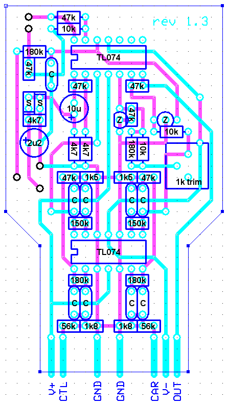
In the EF section, a diode pump charges a capacitor, but a good portion of the control signal leaks through. So I sent the EF's voltage through a low-pass filter consisting of a 4.7k resistor and 1uF capacitor (knee frequency of 34 Hz). This was dumb for a couple reasons. For the lowest channel (center around 45 Hz), it doesn't filter out enough of the control signal, so the control can bleed into the output. For the higher channels (say, 200 Hz and up), it filters out everything, but prevents the voltage from dropping as rapidly as it otherwise could (poor response time to step inputs).

So, I'm incorporating a slight re-design in which the EF's low-pass filter now uses a 180k resistor and a capacitor of value C (the defining capacitor value for that channel, also used in the main band-pass filters for the channel). This leads to new decay time constants and better performance all around. Here is a list of the defining capacitor value, central frequency, and the amount of time for the channel output to decay to 1/10 of its former value (using the new EF filter section) for each channel:
  • 220 nF, 45 Hz, 107 ms
    150 nF, 66 Hz, 78 ms
    100 nF, 99 Hz, 59 ms
    68 nF, 145 Hz, 42 ms
    47 nF, 210 Hz, 39 ms
    33 nF, 299 Hz, 35 ms
    22 nF, 448 Hz, 31 ms
    15 nF, 657 Hz, 26 ms
    10 nF, 986 Hz, 25 ms
    6.8 nF, 1450 Hz, 25 ms
    4.7 nF, 2098 Hz, 25 ms
    3.3 nF, 2988 Hz, 24 ms
    2.2 nF, 4482 Hz, 24 ms
    1.5 nF, 6573 Hz, 23 ms
The lowest channel has a fairly slow response time, but it has much better filtering than before, and the higher channels have significantly improved response time. They should allow rapid percussive sounds to come through well, while still preventing the control signal from bleeding into the channel output. Additionally, instead of a 4.7k resistor loading a 50k potentiometer (not good), it's now a 180k resistor loading a 25k potentiometer (much better). That means when you adjust the band level potentiometer, it will have a much smaller effect on the filtering. You'll be able to hit max level and still filter the control signal just fine.

Finally, here is the new simulation in Falstad's applet:
http://www.falstad.com/circuit/#%24+1+4 ... 05+2+-1%0A

User avatar
lithiumdeuteride
Information
Posts: 25
Joined: 17 Nov 2011, 00:48
Has thanked: 10 times
Been thanked: 5 times

Post by lithiumdeuteride »

The v1.3 layout has been updated with the new values. You can see it here:
http://www.techwarereview.com/non-websi ... 20v1.3.png
Note the 180k resistor and C capacitor in the upper left.

I think I've completed about two thirds of the solder joints so far. Here's a photo showing all of the boards together:
Image

User avatar
lithiumdeuteride
Information
Posts: 25
Joined: 17 Nov 2011, 00:48
Has thanked: 10 times
Been thanked: 5 times

Post by lithiumdeuteride »

I didn't count on such a wide spread of RDS(ON) among the JFETs. I thought they would all lie within 10% of each other, but they turned out to span roughly 60%. Some JFETs were 350 ohms. Others were 570 ohms. The rest were scattered haphazardly in the middle.

With the current design, the trimpots give me only +/-5% adjustment to try to zero the gain of each channel. That meant I had to sort all the JFETs by RDS(ON) value, then choose pairs that were close enough for the trimpot to make up the difference. I ordered 36 JFETs and was barely able to find 14 pairs that were close enough together to zero (within 5% of each other).

A bit of testing with N-channel JFETs shows that they aren't much better than the P-channel ones when it comes to variance in RDS(ON). Still roughly a 50% spread. But if you have only the more common N-channel JFETs, you can swap the direction of the Schottky diodes, LED, and two electrolytic capacitors on each channel board, and the vocoder will work just the same. The JFETs must have the same pinout, of course, or else you'll have to twist them into fancy shapes. But I think the pinout on all JFETs in a TO-92 package is the same. JFETs in this package seem to have been recently discontinued by Fairchild.

If I were to build it again, I'd change the 10k and 180k resistors (which have a parallel resistance of 9.474k) in series with a 1k trimpot to a 10k and 100k (parallel resistance of 9.091k) in series with a 2k trimpot. That means one will need a finer touch with the trimpot to zero the channel gain, but it's vastly easier to find JFETs within 10% of each other than it is to find them within 5% of each other. These changes will be incorporated into the final specification, which I shall of course provide freely to everyone. Can anyone suggest a program to make professional-looking build instructions?

Oh yeah, and the vocoder is finished. It sounds good, better than I was expecting. Photos and audio clips are soon to follow.

User avatar
lithiumdeuteride
Information
Posts: 25
Joined: 17 Nov 2011, 00:48
Has thanked: 10 times
Been thanked: 5 times

Post by lithiumdeuteride »

Here are some photos of the finished assembly (except the XLR jack, which isn't attached yet):
Image
Image
Image
Image

And lastly, here's an audio recording:


The filtered signal path is like so:
Guitar ----> Compressor ----> Distortion ----> Vocoder ----> MBox2 Mini
And the control signal path is like so:
SM-57 ----> Vocoder

User avatar
uncleboko
Cap Cooler
Information
Posts: 509
Joined: 25 Mar 2008, 20:19
Has thanked: 58 times
Been thanked: 41 times

Post by uncleboko »

Brilliant! :D

User avatar
lithiumdeuteride
Information
Posts: 25
Joined: 17 Nov 2011, 00:48
Has thanked: 10 times
Been thanked: 5 times

Post by lithiumdeuteride »

After some research, I decided I designed the multiple feedback bandpass filters improperly. Specifically, I want broadband pink noise to pass through while keeping the same 'typical' voltage amplitude. In other words, the integrated (from 20 Hz to 20 kHz) area under the power spectral density curve for the incoming pink noise should be the same as the area under the outgoing power spectral density curve. Since the filters are narrow in frequency, they must be higher in gain to compensate. I chose a gain which was too low, and a Q which was a bit too high.

I'm increasing the gain of each filter from 1.5 to about 2.7 at the center frequency. I'm also reducing the Q from 5 to 4. This should allow more RMS signal amplitude to get past the filters, which were having a hard time triggering the envelope follower without maxing the input volume (giving it a high noise floor as a result). I was worried about too much gain causing clipping, but with a split supply of +12 and -12 volts, headroom should still be OK.

User avatar
Motter
Solder Soldier
Information
Posts: 163
Joined: 24 Aug 2012, 18:02
Location: New Orleans
Has thanked: 32 times
Been thanked: 121 times

Post by Motter »

That thing sounds great. I don't understand any of the science behind that circuit, but I'm really impressed with the results.

I couldn't tell what they were doing in the video, so I have to ask: what is the purpose of the LEDs? Do they turn on/off as each channel frequency is activated/deactivated (i.e., indicating the range of frequencies in the signal)?

Also, what do the potentiometers do?


Still have PCBs available? I may consider getting one of these after the holidays...

User avatar
lithiumdeuteride
Information
Posts: 25
Joined: 17 Nov 2011, 00:48
Has thanked: 10 times
Been thanked: 5 times

Post by lithiumdeuteride »

I still have two sets of PCBs & edge connectors for sale. The price is $166 + shipping for a complete set, which includes 1 main board, 14 channel boards, and 14 edge connectors. It may sound a bit steep, but that's actually 1/3 of the 'bulk' pricing I paid for the three sets from ExpressPCB and DigiKey, so I'm making no profit. Plus, I'll throw in free tech support (I'm still figuring out the optimal parameters myself!). Expect to spend another $200 on components to populate the boards. There are a hell of a lot of components, though I tried my best to reduce part count as much as possible.

The LEDs activate whenever their respective channels activate, and their brightness should be proportional to the strength of the signal coming through that channel. However, I don't have a video camera. That was merely a static image for the YouTube video. Also, I totally misjudged the brightness of red indicator LEDs and put a 47k resistor in series with them, so they're very dim even when active. They need something more like 4.7k to shine brightly. These changes will be incorporate into the final specification.

The potentiometers allow you to boost or cut different frequency bands. If you want a shrill robot voice, you can mute the low-frequency channels by turning their potentiometers to zero. If you don't want this capability, or want to save money by not buying potentiometers and knobs, you can replace the potentiometers with fixed voltage dividers (10k or 12k resistors, probably).

The basic theory behind a vocoder goes like this:
1. Take an input signal from a microphone, and another input signal from an instrument (say, a synthesizer).
2. Use a bunch of high-Q bandpass filters to split the microphone signal into discrete frequency bands.
3. Use more bandpass filters to split the instrument signal into the same frequency bands.
4. Use envelope followers (EF) to measure the signal strength coming through each microphone filter and turn it into a voltage.
5. Use a voltage-controlled amplifier (VCA) to amplify each filtered instrument signal band, in proportion to the voltage coming from the EF.
6. Sum all of the instrument signals and send them to the output.

A block diagram will be helpful here:
Image

The image shows four vocoder channels, centered on frequencies of 100, 150, 220, and 330 Hz, respectively. None of the microphone signal should ever make it to the output. Instead, you hear only the instrument signal, but filtered according the frequency content of the microphone signal.

User avatar
djlace
Information
Posts: 1
Joined: 27 May 2013, 05:58

Post by djlace »

I'm in. I want to buy a set of boards from you.

User avatar
DrNomis
Old Solderhand
Information
Posts: 6807
Joined: 16 Jul 2009, 04:56
my favorite amplifier: Self-Built Valve Amp Head :)
Completed builds: Dallas Arbiter Fuzz Face,Tone Bender Professional Mk 3,Tone Bender 3-Knob,Baja BK Butler Tube Driver,Baja Real Tube Overdrive,Roger Mayer Octavia,EH Soul Preacher,Tech 21 XXL Distortion,MFOS Weird Sound Generator.
Location: Darwin,Northern Territory Australia
Has thanked: 98 times
Been thanked: 279 times

Post by DrNomis »

Have you checked out the PAIA website?, they sell a PAIA Vocoder kit which I'm thinking of buying one day later on this year..... :thumbsup

Cool demo of your vocoder, it has a pretty clear sound to it, most likely due to the fact that your's has 14 frequency bands, you could also try adding a Sibilance detector to it, which is a feature found in some comercially made Vocoders..... :thumbsup
Genius is not all about 99% perspiration, and 1% inspiration - sometimes the solution is staring you right in the face.-Frequencycentral.

User avatar
lithiumdeuteride
Information
Posts: 25
Joined: 17 Nov 2011, 00:48
Has thanked: 10 times
Been thanked: 5 times

Post by lithiumdeuteride »

I'm making a revised version, which will have a bunch of improvements. I plan to pitch it on Kickstarter as a DIY kit (boards only, or boards + components), which will allow demand to be gauged before committing to a large purchase. Buying in bulk means I will be able to offer the kit at a very modest price, as most of the PCB cost is in the initial setup fee.

Here are the improvements:

1.
It will have a better form factor - 7 larger channel boards housing two channels each, instead of 14 small boards in a long line, so finding an enclosure of the right shape will be easier. Having fewer boards is a bit more cost-efficient. The board layouts are also better, with all resistors laying flat.

2.
It will use operational transconductance amplifiers (specifically, the LM13700) as variable-gain amplifiers, like the famous EMS vocoders did. This eliminates the need to find matched pairs of JFETs and ensures that all channels will behave identically with no tuning required.

3.
It will use a precision full-wave rectifier as the envelope follower, for better sensitivity to quiet sounds. The previous envelope follower had poor sensitivity to quiet sounds, creating a slight gated effect. Response time on the envelope follower is also improved.

4.
It will also have an adjustable high-frequency microphone boost so that sibilants are clearer, as well as the ability to mix some of the mic signal into the output if further clarity is required. These features will go a long way towards making speech intelligible, with very little added complexity or cost.

Locked