Roland - AD-50 ( Double Beat ) [schematic]
I just finished a second one of these. It's such an awesome fuzz. I'm going to box it up with a input cap switch. Choice between 1uf and .068uf. Instead of the rotary tone switch on the output, I will have an output cap blend knob. It's pretty killer...
What diagram did you follow? I have been trying to debug mine without any success..glops wrote:I just finished a second one of these. It's such an awesome fuzz. I'm going to box it up with a input cap switch. Choice between 1uf and .068uf. Instead of the rotary tone switch on the output, I will have an output cap blend knob. It's pretty killer...
-
fuzzbuzzfuzz

- Breadboard Brother
To resurrect this thread (:))...
After scoring an AD-50 remarkably cheap and marveling at its wall of fuzzy goodness (even into a Roland JC-120!), I have only one minor gripe - common with a lot of these wah/fuzzes and that`s the fuzz > wah, cool but not so useful. As the boards are quite separate inside, so can I reverse the order to wah > fuzz, simply by unsoldering the respective wires and reversing them? Easy right?
Thanks
Pics:
http://fuzzbuzzfuzz.blogspot.jp/
-
Nocentelli

- Tube Twister
Information
- Posts: 2222
- Joined: 09 Apr 2009, 07:06
- Location: Leeds, UK
- Has thanked: 1155 times
- Been thanked: 954 times
I also find wah->fuzz is usually best, unless you're deliberately going for that extreme filtered sound. You can easily swap the order just as you've described, though you might need to add some extra runs of new wire to route it, easily enough returned to stock with little or no sign if you're concerned about the effect on potential re-sale value. I'd be tempted to wire the "send to fx" input from the bypass switch to a 3PDT toggle wired as a "juggler" order switcher; Again, if you don't want to screw the original pedal, you could leave this inside set to wah-first with the option to switch it if you feel like screwing around - just put the whole switch and wire assembly in a ziplock bag to prevent shorts. RG keen and Beavis, amongst others, have diagrams+info on juggler circuits.
modman wrote: ↑ Let's hope it's not a hit, because soldering up the same pedal everyday, is a sad life. It's that same ole devilish double bind again...

Yeah I too would like to know this...it is quite a drop in volume when the wah is engaged for sure.electrosonic wrote:I just happened to have my pedal open to replace a broken footswitch when I saw this thread - a little off topic I know.
A common complaint about the original pedal is that the voltage divider at the input to the wah section causes an audible volume drop when the wah is engaged. I have heard people recommend moving the input to the wah to the other side of the 47k input resistor, but this drops the input resistance from 80k (47k+33k) to 33k. What is a better solution? And more generally, why to wahs seem to have such low input resistances?
Andrew.

-
sadrew
- Breadboard Brother
i would suggest to isolate the fuzz section and see if still has the problem
at least you know if the problem is in the fuzz or in the wah circuit and narrow your search
main suspect also might be out of range power supply voltage or cabling problem
let me know if you need more help
at least you know if the problem is in the fuzz or in the wah circuit and narrow your search
main suspect also might be out of range power supply voltage or cabling problem
let me know if you need more help
hey guys
i'm building this using the vero layout. would you guys mind taking a look at my wiring diagram? i've got a couple questions:
1) what is the master out? is it a pot?
2) could someone help me with the 3PDT wiring?
3) does everything else look alright?
i couldn't find a small rotary switch that would fit in the 125B enclosure so i got a pcb mount and am planning on mounting it on a small piece of perfboard. hopefully it's clear what i'm doing in the attached diagram.
many thanks!!
-j
i just sketched out this wiring diagram based on the vero layout:
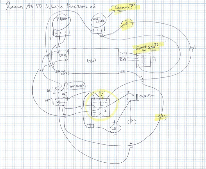
can some kind soul tell me if this is looking good? i highlighted the four areas that i'm not feeling confident about:
- the outlevel wipers 1&2
- the rotary switch (which is going to be a pcb mount rotary on a small piece of perfboard)
- the 3pdt wiring
- the grounding from the vero
i would be extremely grateful for some much needed guidance!
thanks!
-j
-
Nocentelli
- Tube Twister
Information
- Posts: 2222
- Joined: 09 Apr 2009, 07:06
- Location: Leeds, UK
- Has thanked: 1155 times
- Been thanked: 954 times
You can't edit posts, but you can delete the attachment via user control panel->manage attachments. Just make sure you delete the right (wrong) one.
If you post a link to the vero you want to use, we might be able to provide more assistance.
If you post a link to the vero you want to use, we might be able to provide more assistance.
modman wrote: ↑ Let's hope it's not a hit, because soldering up the same pedal everyday, is a sad life. It's that same ole devilish double bind again...
thanks. i deleted the image. hopefully that helps clarify things a bit.Nocentelli wrote:You can't edit posts, but you can delete the attachment via user control panel->manage attachments. Just make sure you delete the right (wrong) one.
If you post a link to the vero you want to use, we might be able to provide more assistance.
here is RnFR's vero layout that i'm using. thanks!
-
Nocentelli
- Tube Twister
Information
- Posts: 2222
- Joined: 09 Apr 2009, 07:06
- Location: Leeds, UK
- Has thanked: 1155 times
- Been thanked: 954 times
Your diagram is pretty close. The labels on the vero sow some seeds of confusion. The three "outs" on the right of the board are the three different tone outputs from the fuzz - they should be wired to the three throws of an SP3T, and the common connected to lug three of the 50k output pot (this is mislabelled as output level 1 on the vero). The switch doesn't need a ground. Lug 1 of the output level pot should be connected to ground where the vero states "output level 3". Lug 2 of the output pot goes to the footswitch as you've drawn it. I'd use sustain pot lugs 2 and 3 (instead of 1 and 2) to make sure gain increases with clockwise.
modman wrote: ↑ Let's hope it's not a hit, because soldering up the same pedal everyday, is a sad life. It's that same ole devilish double bind again...
Very much appreciated! I think I've got it now. Will wire up shortly. Maybe my layout (despite it being sloppily hand-drawn) would be helpful to someone? The only thing I'm unsure about is the sustain pot lugs. I assume lug 2 stays put and what I connected to lug 1 before should be connected to lug 3?Nocentelli wrote:Your diagram is pretty close. The labels on the vero sow some seeds of confusion. The three "outs" on the right of the board are the three different tone outputs from the fuzz - they should be wired to the three throws of an SP3T, and the common connected to lug three of the 50k output pot (this is mislabelled as output level 1 on the vero). The switch doesn't need a ground. Lug 1 of the output level pot should be connected to ground where the vero states "output level 3". Lug 2 of the output pot goes to the footswitch as you've drawn it. I'd use sustain pot lugs 2 and 3 (instead of 1 and 2) to make sure gain increases with clockwise.
Huge thanks and happy new year!
Wiring Diagram v3:

-j
-
Nocentelli
- Tube Twister
Information
- Posts: 2222
- Joined: 09 Apr 2009, 07:06
- Location: Leeds, UK
- Has thanked: 1155 times
- Been thanked: 954 times
Happy new year! Yes, diagram is ok now, but I would disconnect the two ring lugs on the jacks (but leave the input ring connected to power negative): This way, you only need to unplug the input to cut the battery power.
modman wrote: ↑ Let's hope it's not a hit, because soldering up the same pedal everyday, is a sad life. It's that same ole devilish double bind again...