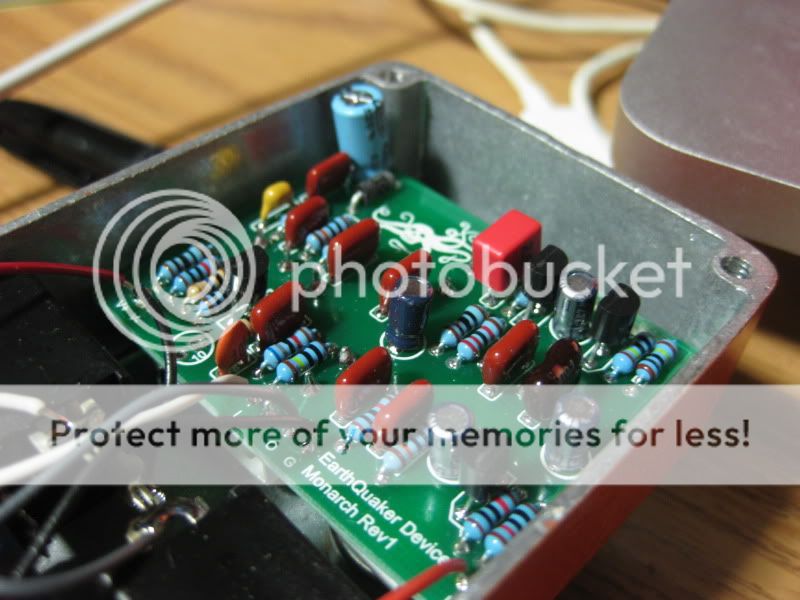
seems like Earhquaker changed to multilayered pcbs lately
I found a lot of seemingly non-collected pads (I marked these blue), which seem to be connected on a non-visible layer, so I guess it wont make sense to put more effort into tracing my friend's board, right?
any ideas are welcome.
not all of them:
there are some other traces on the top-layer of the PCB - i can see two running under the upper row of components
and the upper-left diode is not connected to the top layer... maybe it's really a 3 layers board
...what about taking some other pics from different angles, and one of the other side too?
even if it's a 3 layers board, i don't think it's gonna be too hard now. the first stage (a mosfet, cool idea) is basically traced, the eq part is pretty much understandable and for the rest of the circuit we almost have it. a rough schematic can help to visualize everything.
so, basically, this is a mosfet input stage, eq, a jfet mu-amp and then a jfet buffer with 2 resistors and caps to cut the high end. cool.
what is that wire on the side of B-? i have some doubts on the part between the volume pot and the mu amp but the rest is pretty much figured out.
btw, i don't think this is a 3 layers board at all. the traces that we miss are on the top layer and under the components. the vastly majority of the top layer is ground.
pietro_moog wrote:so, basically, this is a mosfet input stage, eq, a jfet mu-amp and then a jfet buffer with 2 resistors and caps to cut the high end. cool.
what is that wire on the side of B-? i have some doubts on the part between the volume pot and the mu amp but the rest is pretty much figured out.
btw, i don't think this is a 3 layers board at all. the traces that we miss are on the top layer and under the components. the vastly majority of the top layer is ground.
I agree that it's most likely a 2 layer board. got any shots of the bottom of it?
this is a first schematic. maybe someone can work it in a software.
myself, i'm not sure of a few values, like the ones on the bs170, but the schematic should be this.
i have some doubts on the 12k resistor before the eq, it looks like a strange value. can you measure it with a DMM?
and the 1k / 10k resistor from the bs170 leg is probably a 330Ω
this is my RE:
something to verify
please read the notes within the images
Attachments
the arrows indicate the connections to verify
components names match the schematic
marked in BLUE some traces that should be on the top layer, please verify that. Also: all the YELLOW pads should be connected to ground - please verify this with the tester
monarch_nocentelli.gif (23.82 KiB) Viewed 2730 times
modman wrote: ↑Let's hope it's not a hit, because soldering up the same pedal everyday, is a sad life. It's that same ole devilish double bind again...
No, and i'd advise holding fire until the schem has been looked at a bit more closely. Last night through headphones it sounded great, but after a longer play through a few amps at volume it doesn't seem right (to my ears). I've only got linear pots, but even taking that into account i have to crank the bass and roll the treble almost off or it is way too thin and harsh. I'll check over my breadboard layout carefully, but i wouldn't build the vero i posted as is.
modman wrote: ↑Let's hope it's not a hit, because soldering up the same pedal everyday, is a sad life. It's that same ole devilish double bind again...
well, the schematic structure seems pretty reasonable now. the values too. log pots on the eq are pretty much important, you can see by yourself on the duncan simulator. btw, on the bass pot, 2.2nf and 22nd should be switched, 2.2 is between lug 3 and 2. that's a big reason because it doesn't sound right. and the 470pf treble bleeding cap on the gain is more harmful than useless. i cut those even in amps. the last 2 caps, 220pf and 100pf they could be chosen by preference. even the eq could be modeled after personal taste.
anyhow, this pedal looks cool, but it's just a mosfet boost cascading in a fet mu amp with an orange eq in between.
thanks!
looking at the gut shots, it appears that on your layout, the two 100K resistors on the lugs 2&3 of the bass pot should be 10K's. maybe that would give it more low end.
I built up my vero of it and it sounds great. the only thing is, is that it seems to have less gain than the video demos that I've seen. otherwise it's awesome.
if I can find a way to up the drive/dirt, it'll be perfect.