Cool. Maybe John will chime back in and confirm. Thanks for you input lvlark. Oh, and thanks for your blog. Without it I would not be building pedals and would have zero soldering skills.IvIark wrote:Yes that looks like the way John described it, or at least that's how I understood it.
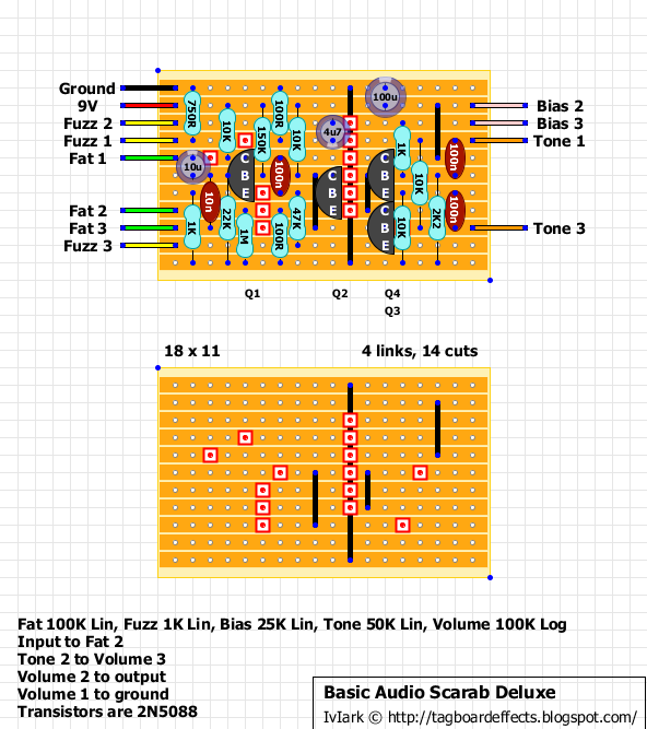
Basic Audio - Scarab Deluxe [traced]
-
storyboardist

- Breadboard Brother
Information
-
IvIark

- Tube Twister
Information
"If anyone is a 'genius' for putting jacks in such a pedal in the only spot where they could physically fit, then I assume I too am a genius for correctly inserting my legs into my pants this morning." - candletears7 - TGP
-
John Lyons

- Solder Soldier
I meant Q4, correct.
Remove C8, put R13 between C7 and ground.
R7 should be 100 ohms.
100 ohms between C5 and ground.
Remove C8, put R13 between C7 and ground.
R7 should be 100 ohms.
100 ohms between C5 and ground.
-
storyboardist
- Breadboard Brother
Information

-
John Lyons
- Solder Soldier
1uf might be enough for you. The cap stores energy as well as passes signal at all frequencies.
I like the sloppiness of 10uf. My goal is to make it as tight and responsive with the .01 and then sloppy
with the 10uf. So you set the FAT knob as you like. 10uf has a good bit of thump to it...
I like the sloppiness of 10uf. My goal is to make it as tight and responsive with the .01 and then sloppy
with the 10uf. So you set the FAT knob as you like. 10uf has a good bit of thump to it...
-
IvIark
- Tube Twister
Information
So does Q4 base and collector connect to the bias resistor? That looks peculiar to me.
"If anyone is a 'genius' for putting jacks in such a pedal in the only spot where they could physically fit, then I assume I too am a genius for correctly inserting my legs into my pants this morning." - candletears7 - TGP
-
IvIark
- Tube Twister
Information
Get some of the 106 multilayer ceramics like these.roseblood11 wrote:Why is C1 so big? Wouldn't 1µF sound exactly the same? I don't like electrolytics in the signal path...
"If anyone is a 'genius' for putting jacks in such a pedal in the only spot where they could physically fit, then I assume I too am a genius for correctly inserting my legs into my pants this morning." - candletears7 - TGP
-
IvIark
- Tube Twister
Information
Just going back to this, I'm assuming the Bias pot just connects to Q3 collector, and Q4 collector actually connects straight to the supply. That would then be in keeping with the Hot Silicon.IvIark wrote:So does Q4 base and collector connect to the bias resistor? That looks peculiar to me.
"If anyone is a 'genius' for putting jacks in such a pedal in the only spot where they could physically fit, then I assume I too am a genius for correctly inserting my legs into my pants this morning." - candletears7 - TGP
-
Nocentelli

- Tube Twister
Information
- Posts: 2222
- Joined: 09 Apr 2009, 07:06
- Location: Leeds, UK
- Has thanked: 1155 times
- Been thanked: 954 times
I thought it looked odd, and also assume the Q4 collector is only connected to +9v. If the collector and base were shorted, wouldn't it just be a diode?IvIark wrote:Just going back to this, I'm assuming the Bias pot just connects to Q3 collector, and Q4 collector actually connects straight to the supply. That would then be in keeping with the Hot Silicon.IvIark wrote:So does Q4 base and collector connect to the bias resistor? That looks peculiar to me.
modman wrote: ↑ Let's hope it's not a hit, because soldering up the same pedal everyday, is a sad life. It's that same ole devilish double bind again...
-
~arph

- Cap Cooler
Please add your name to the image, so it doesn't look like it was just mestoryboardist wrote:Thanks John! Here's the final schematic.
https://i756.photobucket.com/albums/xx2 ... 906ef3.jpg
In the quiet words of the virgin Mary: "Come again?"
-
storyboardist
- Breadboard Brother
Information
I did. Team effort!~arph wrote:Please add your name to the image, so it doesn't look like it was just me
Here's the schem again, hopefully in its final form, with the Bias control moved to effect only Q3.

-
IvIark
- Tube Twister
Information
"If anyone is a 'genius' for putting jacks in such a pedal in the only spot where they could physically fit, then I assume I too am a genius for correctly inserting my legs into my pants this morning." - candletears7 - TGP
-
John Lyons
- Solder Soldier
The 10k/.1/2k2 is the low pass filter. The 50k pot pans between a low pass and tone network bypass (for the most part)~arph wrote:Why not replace the tone pot with a 10k and leave out R13? (or am I missing something? it's still early)
Imagine the big muff tone network with only the low pass side.
-
IvIark
- Tube Twister
Information
I think what ~arph was saying is that because the 10K is in parallel with the tone pot, it's just like having an 8.3K tone pot, so why not just omit the 10K resistor and use a 10K for the pot.
"If anyone is a 'genius' for putting jacks in such a pedal in the only spot where they could physically fit, then I assume I too am a genius for correctly inserting my legs into my pants this morning." - candletears7 - TGP
-
~arph
- Cap Cooler
YupIvIark wrote:I think what ~arph was saying is that because the 10K is in parallel with the tone pot, it's just like having an 8.3K tone pot, so why not just omit the 10K resistor and use a 10K for the pot.
In the quiet words of the virgin Mary: "Come again?"
-
John Lyons
- Solder Soldier
Ok, I see it now. Paralleling the pot changes the taper as well.
Cheaper to use a 50KB pot rather than a 10KC...
The 10k resistor is only a couple cents. A 10KC pot is $1.50 or so.
Cheaper to use a 50KB pot rather than a 10KC...
The 10k resistor is only a couple cents. A 10KC pot is $1.50 or so.
-
~arph
- Cap Cooler
Yes, you can influence taper, but shouldn't the 10k be connected to the wiper instead of the low side of the pot to simulate a reverse log action? The way it's connected now just makes the 50kB pot a 8.3kB pot.
In the quiet words of the virgin Mary: "Come again?"
-
storyboardist
- Breadboard Brother
