Spaceman WOW Signal  [traced]

General documentation, gut shot, schematic links, ongoing circuit tracing, deep thoughts ... all about boutique stompboxes.
Post Reply
User avatar
digi2t
Degoop Doctor
Information
Posts: 284
Joined: 09 Feb 2011, 15:10
Has thanked: 54 times
Been thanked: 385 times

Post by digi2t »

There's now a video out;


I now have one on my bench. Here are some teaser shots;

Image

Image

The tracing has begun.......
No matter how many times I cut it, it`s STILL too short!

https://www.deadendfx.com/

User avatar
night-butterfly
Information
Posts: 20
Joined: 10 Nov 2010, 05:48
Has thanked: 10 times
Been thanked: 11 times

Post by night-butterfly »

IC + russian GE, switchable clipping... A polystyrene cap like in the spaceman and a really clean gut too! Can't wait for a schematic :D

User avatar
Duckman
Opamp Operator
Information
Posts: 1492
Joined: 20 May 2009, 01:45
Has thanked: 320 times
Been thanked: 134 times

Post by Duckman »

Seems like (in the video) the switch change the depth... some tremolo included...
All cables trough PCB... nice detail. Very neat.

User avatar
devastator
Cap Cooler
Information
Posts: 675
Joined: 19 Jul 2008, 16:00
Location: France
Has thanked: 8 times
Been thanked: 22 times

Post by devastator »

Nice !

Seems to be simpler than I thought. I don't know why but I thought that was a kind of fuzz with a ring mod .

Looks like a fuzz followed by a tremolo circuit.

User avatar
agoldoor
Breadboard Brother
Information
Posts: 112
Joined: 26 May 2011, 04:37
Has thanked: 39 times
Been thanked: 21 times

Post by agoldoor »

It's so... space-age-y!! Love it!

User avatar
juanro
Cap Cooler
Information
Posts: 488
Joined: 01 Jun 2009, 17:07
Location: Argentina
Has thanked: 51 times
Been thanked: 117 times

Post by juanro »

The undulating pcb traces are a really classy touch...

Juanro
La única verdad es la realidad.

User avatar
ppluis0
Diode Debunker
Information
Posts: 915
Joined: 14 Jul 2010, 18:33
Location: Argentina
Has thanked: 127 times
Been thanked: 299 times

Post by ppluis0 »

juanro wrote:The undulating pcb traces are a really classy touch...
It looks as if the designer knew the guts of his creations would sooner or later be posted and discussed here... :mrgreen:

BTW, I like the strain hole to reinforce the wires when they came out of the board.

Cheers,
Jose

User avatar
LaceSensor
Cap Cooler
Information
Posts: 585
Joined: 02 Jan 2011, 12:01
Has thanked: 57 times
Been thanked: 277 times

Post by LaceSensor »

sounds a like an average fuzz into a DOD vibrothang
not my cup of tea

User avatar
devastator
Cap Cooler
Information
Posts: 675
Joined: 19 Jul 2008, 16:00
Location: France
Has thanked: 8 times
Been thanked: 22 times

Post by devastator »

any news of that spaceman pedal ? :D

User avatar
digi2t
Degoop Doctor
Information
Posts: 284
Joined: 09 Feb 2011, 15:10
Has thanked: 54 times
Been thanked: 385 times

Post by digi2t »

devastator wrote:any news of that spaceman pedal ? :D
It's on my bench... along with 3 other projects. It's number 2 in the cue. I have it apart, I just need to start tracing now.

Here's a pic of the backside for now;
Image
No matter how many times I cut it, it`s STILL too short!

https://www.deadendfx.com/

User avatar
Whoismarykelly
Resistor Ronker
Information
Posts: 395
Joined: 22 Oct 2007, 18:26
Has thanked: 6 times
Been thanked: 17 times

Post by Whoismarykelly »

Little tricky with the opto under the board there.

User avatar
digi2t
Degoop Doctor
Information
Posts: 284
Joined: 09 Feb 2011, 15:10
Has thanked: 54 times
Been thanked: 385 times

Post by digi2t »

OK, I finally got around to tracing the board. Lots of unknowns, since they went the extra mile to grind/erase/dissolve the numbers on the IC's, transistors, and one cap. Even the Vactrol has been erased. Anywho, here is what I have so far;

Image

Any ideas on the unknowns?
No matter how many times I cut it, it`s STILL too short!

https://www.deadendfx.com/

User avatar
digi2t
Degoop Doctor
Information
Posts: 284
Joined: 09 Feb 2011, 15:10
Has thanked: 54 times
Been thanked: 385 times

Post by digi2t »

Here's a schematic for now.

Image

Going to play with the fuzz side on the breadbaord first. See if I can "juice" it up a bit.
No matter how many times I cut it, it`s STILL too short!

https://www.deadendfx.com/

User avatar
digi2t
Degoop Doctor
Information
Posts: 284
Joined: 09 Feb 2011, 15:10
Has thanked: 54 times
Been thanked: 385 times

Post by digi2t »

Here's an initial vero offer. I'm mounting the LFO speed switch on the outside as a toggle, and I've added a footswitch to turn the LFO off. As always, not verified, until I build it, but I always put them out there for the eyes to spot errors.

Image

Going to do a check trace tonight, but if anyone spots anything, please pipe up.

Cheers,
Dino
No matter how many times I cut it, it`s STILL too short!

https://www.deadendfx.com/

User avatar
digi2t
Degoop Doctor
Information
Posts: 284
Joined: 09 Feb 2011, 15:10
Has thanked: 54 times
Been thanked: 385 times

Post by digi2t »

OK, after trace checking, here are the corrected schematic and vero. The vero is still unverified, but it matches the PCB trace, so I'm fairly confident that it should be alright.

EDIT: def schematic and layout here viewtopic.php?f=7&p=211511#p211429

Going to start putting it together this week, and I'll update when it's done.

Cheers,
Dino
No matter how many times I cut it, it`s STILL too short!

https://www.deadendfx.com/

User avatar
digi2t
Degoop Doctor
Information
Posts: 284
Joined: 09 Feb 2011, 15:10
Has thanked: 54 times
Been thanked: 385 times

Post by digi2t »

Alrighty... been on the bread board awhile, but I finally got it done. Here is the schematic, and the verified vero;

Image

Image

C8 should be tailored to taste, and VR1 replaces the 16K resistor that is in the original. These two components tailor the Vactrol to the circuit. The VTL5C3 works great, although I'm thinking that a VTL5C1 might be what's in the original. In any case, adjusting C8, and using a 25K trimmer allows for adjustment to get a variety of Vactrol or LED/LDR combos to work here. Set the trimmer with the speed toggle on double speed, with the depth set to max, and the speed to max. Dial the trimmer to get a good square wave chop, and test the result by slowly dialing the speed down. The chop should be good throughout the speed range. As for the cap, test between 820pF to 2200pF (or higher if you wish), to get a good balance between the high and low frequency in the wave. Your ears will guide you. My unit is at 2200pF, and a side by side test says pretty well spot on to the original.

IC1 is an MC4558 (or RC4558), and IC2 is a TL072. Besides sounding good, the unit takes a moment to come to life, just like the original, so I believe that I have a good combo here. A TL072 in IC1 WILL NOT WORK!! It's as if the IC latches up when power is applied, and no sound comes out of it. The 4558's don't have this problem. Even a NE5532 works alright here.

Video will be posted tomorrow, A/B'ing the two. It's not cased, but it's operational. I'm still short a 62K resistor, so I'm using two resistors in series right now. It's not a fuzz for everyone, but with the LFO dialed down, still sounds pretty good. The fuzz section alone is worth the build.
No matter how many times I cut it, it`s STILL too short!

https://www.deadendfx.com/

User avatar
digi2t
Degoop Doctor
Information
Posts: 284
Joined: 09 Feb 2011, 15:10
Has thanked: 54 times
Been thanked: 385 times

Post by digi2t »

Crap, I forgot to post the video...

Here you go. Sorry about my long-windedness, just finished a 12 hour night shift. :roll:

No matter how many times I cut it, it`s STILL too short!

https://www.deadendfx.com/

User avatar
johnk
Resistor Ronker
Information
Posts: 282
Joined: 05 Apr 2010, 07:33
Has thanked: 36 times
Been thanked: 293 times

Post by johnk »

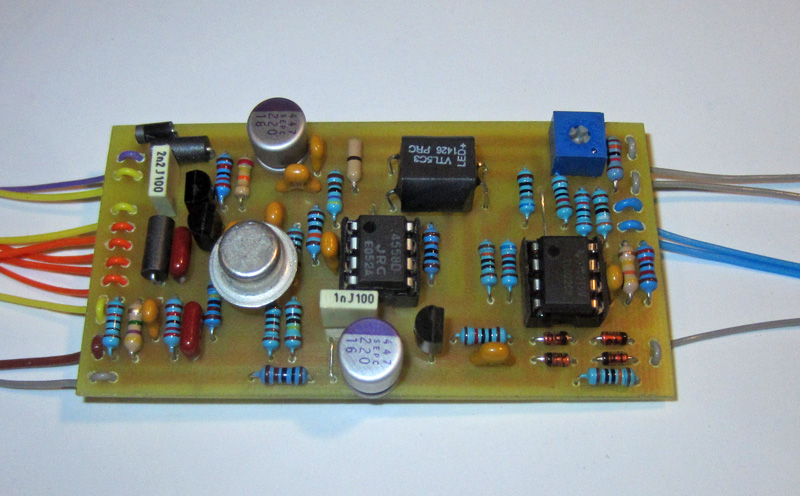
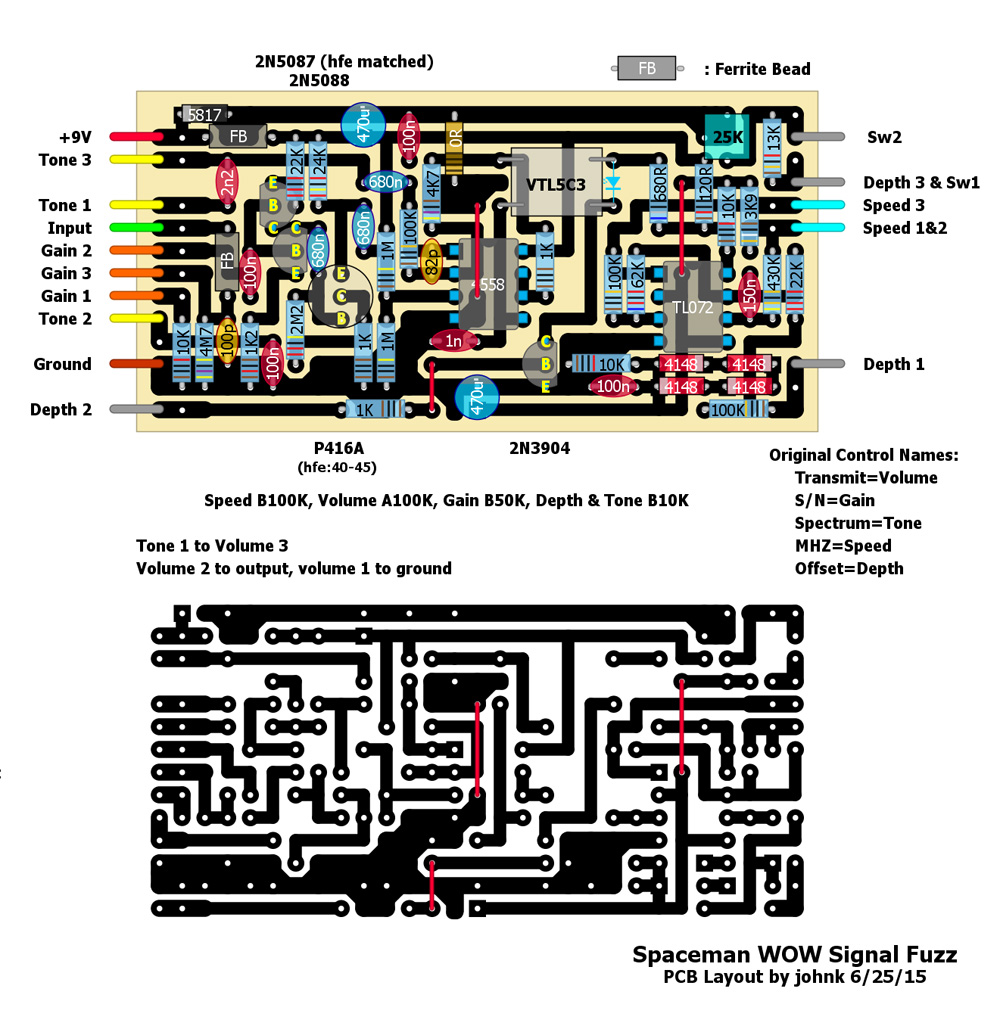
I finally got around to etching a PCB for this one today. I built it up and tested it and it works & sounds just like the original. thanks for posting it digi2T!

pic of the tested pcb:
Image

and the layout:
Image

User avatar
johnk
Resistor Ronker
Information
Posts: 282
Joined: 05 Apr 2010, 07:33
Has thanked: 36 times
Been thanked: 293 times

Post by johnk »

..............and done. in a 1590B with relayed true bypass.

Image

gut shot:
Image

User avatar
digi2t
Degoop Doctor
Information
Posts: 284
Joined: 09 Feb 2011, 15:10
Has thanked: 54 times
Been thanked: 385 times

Post by digi2t »

Super nice build. Love the etch.
No matter how many times I cut it, it`s STILL too short!

https://www.deadendfx.com/

Post Reply