Tech21 SansAmp PSA-1 PCB traces and schematics  [traced]

General documentation, gut shot, schematic links, ongoing circuit tracing, deep thoughts ... all about boutique stompboxes.
User avatar
av500
Information
Posts: 23
Joined: 27 Sep 2013, 18:02
Has thanked: 12 times
Been thanked: 26 times

Post by av500 »

Hi there,

this is first post here on this forum, I hope I'm doing this right.

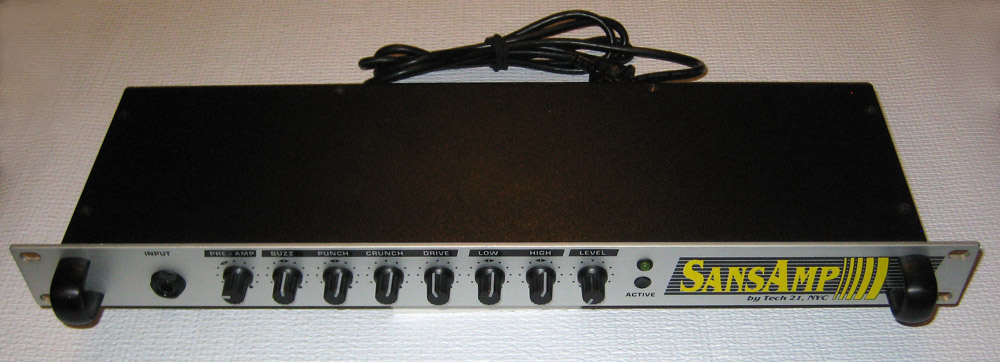
Since nobody seems to have done this before and I was sick in bed for a week recently, I used that time to trace the schematics of the SansAmp PSA-1. One "tiny" part is missing and that's the "mystery" circuit inside the black box used for the CRUNCH and DRIVE. I assume it's based around yet another 072 dual opamp since there are +5V/-5V going into the black box. Anybody with an x-ray?

I did not trace the digital part as that's rather boring. In the end there are only 5 control lines that go to the analog part, two go to the 4053 analog multiplexer of which one switches the bypass signal and the other seems unused. The other three control the four 100k DS1267 dual digital potentiometers which are daisy chained together so that only three control signals are needed.
sansamp_psa1_PCB_top_left.jpg
sansamp_psa1_PCB_top_right.jpg
sansamp_psa1_page1.png
sansamp_psa1_page2.png
sansamp_psa1_page3.png
sansamp_psa1_page4.png
sansamp_psa1_page5.png

User avatar
jsaily
Information
Posts: 23
Joined: 18 Jun 2011, 16:05
Has thanked: 7 times
Been thanked: 19 times

Post by jsaily »

The 27C64 chip is a 64k (8k x 8-bit) EPROM which is not too hard to dump and clone since it cannot be write protected like modern microcontroller internal memories. It's truly old school device (I'd imagine early 90's) with a 68HC processor ;-)

User avatar
elkulon
Breadboard Brother
Information
Posts: 59
Joined: 04 Feb 2012, 19:22
Has thanked: 17 times

Post by elkulon »

Actually, about the mistic IC, Tech21 uses TLCs (CMOS rail-to-rail opamps, from Texas Instruments) often in their designs.
I believe that's the reason to go for +-5V, since those opamps get fried above +-8V (or 16V, whatever you want to name it). Otherwise, I believe that there should not be reasonable to supply a regular 072 with that low voltage. Unless "that" would be the real trick of the "machine".

Anyway, thanks for taking the time and share.

Hope you'll feel better.

User avatar
av500
Information
Posts: 23
Joined: 27 Sep 2013, 18:02
Has thanked: 12 times
Been thanked: 26 times

Post by av500 »

elkulon wrote:Actually, about the mistic IC, Tech21 uses TLCs (CMOS rail-to-rail opamps, from Texas Instruments) often in their designs.
I believe that's the reason to go for +-5V, since those opamps get fried above +-8V (or 16V, whatever you want to name it). Otherwise, I believe that there should not be reasonable to supply a regular 072 with that low voltage. Unless "that" would be the real trick of the "machine".

Anyway, thanks for taking the time and share.

Hope you'll feel better.
Yes, I'm better, thanks.

Interesting about the TLCs. Actually I was expecting some "wonder" opamps inside Tech21 stuff, so I was surprised by the 072s, but maybe the real secret is only in the magic box

User avatar
aquataur
Solder Soldier
Information
Posts: 161
Joined: 21 Mar 2010, 17:41
Location: Innsbruck, Austria
Has thanked: 4 times
Been thanked: 27 times
Contact:

Post by aquataur »

av500 wrote: but maybe the real secret is only in the magic box
There is some interesting read in Teemu Kyttälä´s book, that is available online about the Sansamp series.

As he sais:
SansAmp products rely strictly on such “heresy” as overdriving OpAmps.
There is no universal “SansAmp circuit” and thus the insight is limited to SansAmp GT2. However, what are universal are the approaches and methods of tone shaping used in the concerned circuit
Is looks quite intelligent what they have achieved with a little (or a lot of) careful thinking.

have fun,

-helmut

User avatar
DimebuGG
Solder Soldier
Information
Posts: 218
Joined: 02 Sep 2008, 11:37
Location: Doha, Qatar
Has thanked: 8 times
Been thanked: 198 times
Contact:

Post by DimebuGG »

That mystery circuit in the black box would be like....you bet?.. :)
Attachments
crunchdrivespeakersim.png
Finch: A witty saying proves nothing - Voltaire
Stifler: Suck my dick - Ron Jeremy

User avatar
DimebuGG
Solder Soldier
Information
Posts: 218
Joined: 02 Sep 2008, 11:37
Location: Doha, Qatar
Has thanked: 8 times
Been thanked: 198 times
Contact:

Post by DimebuGG »

Schematic redrawn...
Attachments
Sansamp PSA 1 sch.pdf
(37.25 KiB) Downloaded 1455 times
Finch: A witty saying proves nothing - Voltaire
Stifler: Suck my dick - Ron Jeremy

User avatar
teemuk
Breadboard Brother
Information
Posts: 147
Joined: 17 Aug 2009, 19:54
Has thanked: 3 times
Been thanked: 55 times

Post by teemuk »

Rail-to-rail opamps can be expected to have somewhat better overdrive and clipping recovery characteristics than generic opamps because... well... rail-to-rail pretty much means you'll be clipping things right after the linear area of operation ends. So, they don't likely invert phase like some particular opamps, or display ringing, hysteresis, rail-sticking, etc. That would add much obtrusive higher order harmonics than just generic and "well-behaving" hard clipping.

So... even because it may advertise MOSFETs or "hybrid F.E.T. circuitry" don't expect "soft clipping" or anything fancy. It isn't rail-to-rail device if the amplification doesn't stay absolutely linear from rail-to-rail. And after that the device mandatorily hard clips. For a precision device like opamp soft clipping characteristics would be absolutely ridiculous concept. Not to mention, they are wrapped inside a loop of negative feedback at high magnitude.

But... from a MOSFET -based opamp you can expect better overall noise figures (nice feature for an overdrive circuit which inherently tends to have ludicrous gain) and moderately low slew rates, which can eliminate some harshest overtones of square-wave-ish clipping.

From that to another topic: Those diodes... In back-to-back configuration like that they pretty much have to be Zener type. What's the Zener voltage? Close to supply rails or much lower? It's a somewhat important detail.

User avatar
aquataur
Solder Soldier
Information
Posts: 161
Joined: 21 Mar 2010, 17:41
Location: Innsbruck, Austria
Has thanked: 4 times
Been thanked: 27 times
Contact:

Post by aquataur »

Teemu,

This is a little aside. On this model I don´t see the "amp model" switching circuitry you mention in your book. I wondered where the 1k notch comes from on the "Tweed" model. I found no reference for that whatsoever.

-helmut

User avatar
Stephanovitch
Information
Posts: 46
Joined: 19 May 2011, 06:04
Has thanked: 3 times
Been thanked: 46 times

Post by Stephanovitch »

An important consideration in the redrawn schematic of Dimebugg is clipping diode in 3 OPA feedback who are 3V3 zener diodes.
I see some mistakes on capacitors values next to Drive and Crunch control .
I will try to scan a corrected version next days.
I remember that I have a radiographie of the black box on the PCB but impossible to find it again.
I had traced note on it and I have found same desing than the GT2 filter schematic (right on the DimBugg schematic)

User avatar
av500
Information
Posts: 23
Joined: 27 Sep 2013, 18:02
Has thanked: 12 times
Been thanked: 26 times

Post by av500 »

DimebuGG wrote:Schematic redrawn...
wow, thanks for redrawing this! :applause: :applause: :applause:

User avatar
av500
Information
Posts: 23
Joined: 27 Sep 2013, 18:02
Has thanked: 12 times
Been thanked: 26 times

Post by av500 »

teemuk wrote: From that to another topic: Those diodes... In back-to-back configuration like that they pretty much have to be Zener type. What's the Zener voltage? Close to supply rails or much lower? It's a somewhat important detail.
thanks for the insight, I'll have a look at the zeners and report back here.

One thing that I forgot to mention is what prompted me to undertake all this which is the frequency response of the PSA1 in "flat" configuration. Even with all pots in "normal" position there is this strong falloff at around 7kHz which I noticed comparing it to another preamp when playing bass. The PSA sounded "muffled" to me so I started looking for that lowpass filter and a way to disable it. sadly it seems to be inside the black box :(
Screenshot_2014-12-11-20-50-43.png

User avatar
av500
Information
Posts: 23
Joined: 27 Sep 2013, 18:02
Has thanked: 12 times
Been thanked: 26 times

Post by av500 »

teemuk wrote: From that to another topic: Those diodes... In back-to-back configuration like that they pretty much have to be Zener type. What's the Zener voltage? Close to supply rails or much lower? It's a somewhat important detail.
I just checked, the diodes are marked 1N5230B which makes them 4.7V types: http://uk.farnell.com/fairchild-semicon ... dp/1537820

User avatar
Repairer
Information
Posts: 5
Joined: 21 Jul 2015, 06:00

Post by Repairer »

Hi,
Am trying to repair a PSA1. Any hints would be appreciated.

PSA1 given to me to look at after a replacement transformer burnt out within 2 minutes of powering on. Trying to troubleshoot with 2 multimeter's and a basic level of electronics understanding, so is not very effective at all, want to repair it so that I can buy it.

Initial Problem.
Secondary winding to the analogue power supply side burnt out. Digital side appears to work OK. Guitar plugged into input and output taken to valve amp produces sound akin to an earthed connection.

Fix attempts to date
Have replaced all power supply circuit caps, diodes, and voltage regulators (except for small 79L05 reg), and added new transformer.

Powering is done with no inputs or outputs and all pots turned full to the left.

Two symptoms have presented. Initially the transformer secondary winding became too hot to hold after 20-30 seconds of power on. Digital side of device appeared to work OK. No other heating effect was observed. After troubleshooting one night device was left unpowered. Upon switching on the next morning the voltage regulator feeding the +15 volt rail became too hot to touch after 20 seconds and the transformer is now no longer overheating. Transformer has been checked and its AC outputs are OK.

:hmmm:

User avatar
av500
Information
Posts: 23
Joined: 27 Sep 2013, 18:02
Has thanked: 12 times
Been thanked: 26 times

Post by av500 »

remove the transformer and then measure the resistance to ground of the +/- 15V supplies. The transformer and regulator overheating means that you most likely have a short circuit to ground.

if you indeed find a short, the game is to find what part causes it. remove all caps first, they can go bad easily.
Repairer wrote:Hi,
Am trying to repair a PSA1. Any hints would be appreciated.

PSA1 given to me to look at after a replacement transformer burnt out within 2 minutes of powering on. Trying to troubleshoot with 2 multimeter's and a basic level of electronics understanding, so is not very effective at all, want to repair it so that I can buy it.

Initial Problem.
Secondary winding to the analogue power supply side burnt out. Digital side appears to work OK. Guitar plugged into input and output taken to valve amp produces sound akin to an earthed connection.

Fix attempts to date
Have replaced all power supply circuit caps, diodes, and voltage regulators (except for small 79L05 reg), and added new transformer.

Powering is done with no inputs or outputs and all pots turned full to the left.

Two symptoms have presented. Initially the transformer secondary winding became too hot to hold after 20-30 seconds of power on. Digital side of device appeared to work OK. No other heating effect was observed. After troubleshooting one night device was left unpowered. Upon switching on the next morning the voltage regulator feeding the +15 volt rail became too hot to touch after 20 seconds and the transformer is now no longer overheating. Transformer has been checked and its AC outputs are OK.

:hmmm:

User avatar
bajaman
Old Solderhand
Information
Posts: 4544
Joined: 26 Jun 2007, 21:18
Location: New Brighton, Christchurch, NZ
Has thanked: 593 times
Been thanked: 2049 times

Post by bajaman »

before you remove all the caps power it up and put your finger on the op amps - if you find one getting very hot power down and replace it :secret:
be kind to all animals - especially human beings

User avatar
Repairer
Information
Posts: 5
Joined: 21 Jul 2015, 06:00

Post by Repairer »

Hi av500 and bajaman

Thanks for replying. Have yet to perform your suggestions. Will let you know what I find.

Further question, av500, on your sketch of the amplifiers circuits you list the unknown IC's (ones with the code ground off) as DS1267.

I'm sure that somewhere else on a forum (perhaps this one) I saw that conjecture was that these "unknown" IC might be opamps.

Can you expand on how you determined what these chips were, i.e. were you lucky enough to have a still decipherable code on one of your IC or did you figure it out by testing inputs and outputs; if so how confident are you that you are correct.

I ask because one of the things that atttract me to this device is the ability to be able to secure any future repairs caused by failures by sourcing its cheap component spares whilst still available (as well as its alleged great performance (yet to hear for obvious reasons)).

Repairer

User avatar
av500
Information
Posts: 23
Joined: 27 Sep 2013, 18:02
Has thanked: 12 times
Been thanked: 26 times

Post by av500 »

Repairer wrote:Further question, av500, on your sketch of the amplifiers circuits you list the unknown IC's (ones with the code ground off) as DS1267.

I'm sure that somewhere else on a forum (perhaps this one) I saw that conjecture was that these "unknown" IC might be opamps.

Can you expand on how you determined what these chips were, i.e. were you lucky enough to have a still decipherable code on one of your IC or did you figure it out by testing inputs and outputs; if so how confident are you that you are correct.

I ask because one of the things that atttract me to this device is the ability to be able to secure any future repairs caused by failures by sourcing its cheap component spares whilst still available (as well as its alleged great performance (yet to hear for obvious reasons)).

Repairer
they are not opamps, because they are not connected as opamps and make no sense as such. the opamps are the TL072 8-pin parts and are labeled as such on my unit. since the device is digitally controlled you need something to do the actual control and that's where the digital potentiometers come into play. I did some educated guessing what these parts were and then compared data sheets and pinouts until I had a match. the fact that three digital control lines are daisy chained between these 4 chips don't leave much room for other interpretation of what these are. the later PSA1.1 model swaps these for a different set of potentiometer chips, I would have to lookups which ones.

User avatar
Repairer
Information
Posts: 5
Joined: 21 Jul 2015, 06:00

Post by Repairer »

Hi av500
Cheers for the additional info, you are obviosuly streets ahead of me with your knowledge.

Hi Bajaman
I tried the finger on the op amp test. Very subjective, some I thought were slightly warming but on subsequent test could not confirm first observations. Was trying to scheme how I could obtain a thermal camera, the slim chance of doing this all went to pear shape when I forgot to take the new transformer with me to my former workplace, bit hard to warm anything with no transformer. Lesson..... don't repack bags 1 hour before leaving for airport.

Anyhow I am leaning towards it being a cap problem. Found out more info on the psa1's history. Apparently it had been sitting unused for quite some time. Then promptly failed upon use....drying cap???, though none have actually exploded. A cap problem could also explain the shift in symptoms now that I have been stuffing around with it, that perhaps the dodgy cap has reformed slightly. Now have my scope and cap tester handy. Need to find time to get onto it. I am tempted to just replace all op amps though as far easier to desolder and resolder 64 IC leg joints than all those caps.

Will post again once I have made some progress.

Repairer

User avatar
56335130
Information
Posts: 22
Joined: 01 Aug 2010, 11:12
Has thanked: 1 time
Been thanked: 9 times

Post by 56335130 »

aquataur wrote:Teemu,

This is a little aside. On this model I don´t see the "amp model" switching circuitry you mention in your book. I wondered where the 1k notch comes from on the "Tweed" model. I found no reference for that whatsoever.

-helmut
The first sansamp(which means without amp) is the sansamp classic.and then the gt2 ,tri.ac,and others. these pedal guitar amp and cab simulator all have those amp type and cab type switcher (for switching preamp lpf,hpf,eq and post amp eq trick
to simulate the guitar amp and cab styles.

The other hand was the sansamp rack series.the sansamp original psi(without the digital presets' psa),the psa1.0 and the preamp RPM(with less crunch option I think).these thinks uses knobs instead of switches to dial the shape of the eq instead of the RC switching method.

Image
If one wants to unserstand the sansamp psa,this model is really the analog psa :evil:

Post Reply