Hi men! Have anyone a PCB of this https://www.freestompboxes.org/viewtopic ... 20#p117656,
or this https://www.freestompboxes.org/viewtopic ... 208#p72618. Thanks!
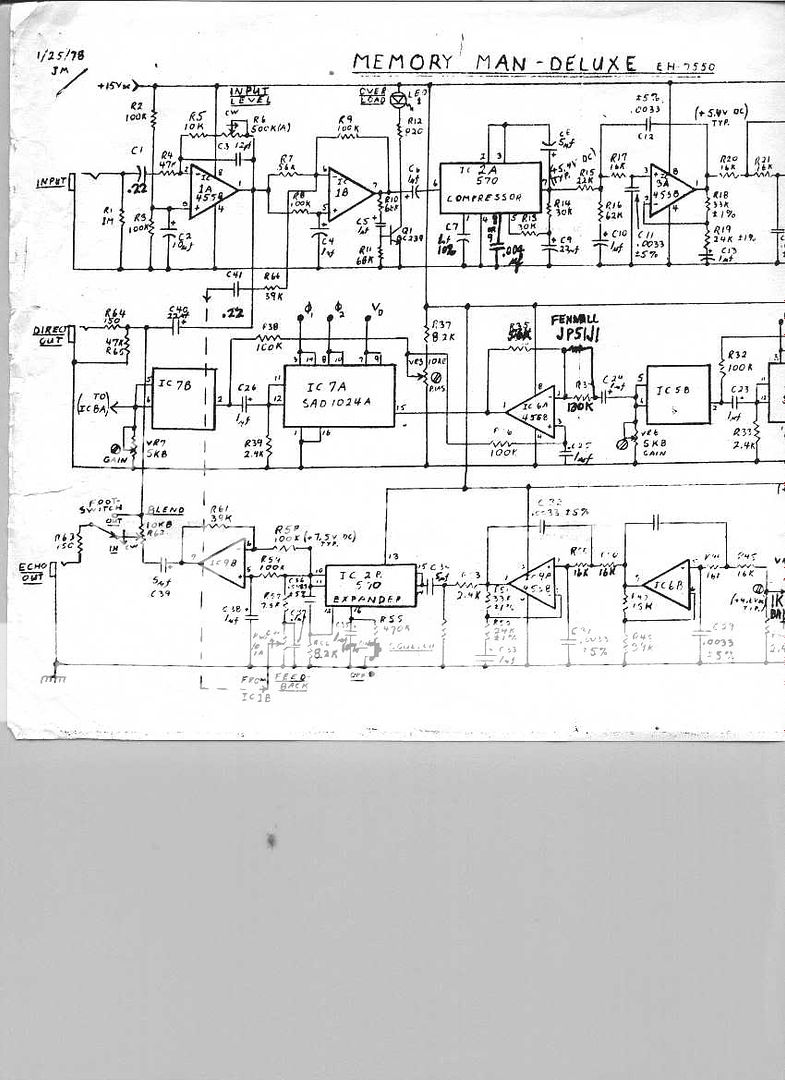
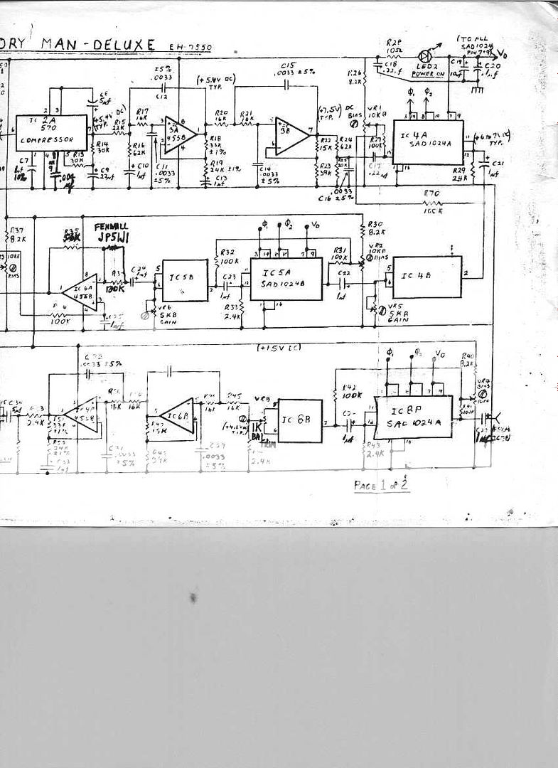
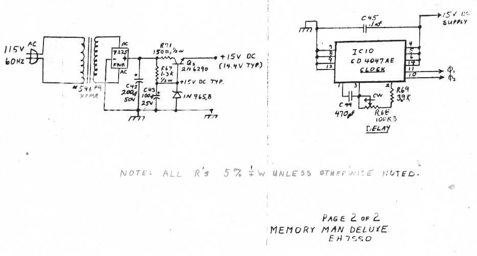
EHX - Deluxe Memory Man (SAD 1024A) EH7550 [schematic]
-
rasta_maleek

- Resistor Ronker
I buy (150€) deluxe memory man vintage( I think reissue) I will inner photos if you want it, it has build in transformer.
Resurrecting an old thread here. Does anyone have the schematic and/or possible service manuals etc. for the EC2002_REV_E Deluxe Memory Man? If possible, PM me or mail me at starkjo@gmail.com . I'd appreciate it a lot!
Another noob question - in some pics in this thread, the MN3008 chips have the number 7 on them, while mine have the number 3 (in addition to "MN3008" and "0.0"). What do the 7s or 3s mean?
Another noob question - in some pics in this thread, the MN3008 chips have the number 7 on them, while mine have the number 3 (in addition to "MN3008" and "0.0"). What do the 7s or 3s mean?
-
Dirk_Hendrik

- Old Solderhand
Information
Thanks a bunch, Dirk! Really appreciate it.
I'm gonna go thru it to see if there are any changes from the schematic you pointed out, to my REV_E board, but if there turn out to be any changes, they'll probably be minor.
Great stuff.
I'm gonna go thru it to see if there are any changes from the schematic you pointed out, to my REV_E board, but if there turn out to be any changes, they'll probably be minor.
Great stuff.
-
Dirk_Hendrik
- Old Solderhand
Information
A board revision does not necessarily mean a schem revision as well. Considering the DMM design is rather old chances on dramatic circuit changes are really small.

Information
Thanks a lot.guiltyspark wrote:I have one of these memory man RI's also, I like it a lot. Mine also clips with just about any guitar. I found this post on another forum and have been meaning to try it, any comments?
Now, the stock input impedence is really low and there's a ton of potential gain on tap - much more than is needed, even using the DMM as a boost. So replace the 100K resistor in the input with a 1M pot. Here's the schematic: http://www.freeinfosociety.com/electron ... php?id=381.
The stock gain structure has a 100K resistor before the opamp and a 1M pot in the feedback loop (this is the volume pot). By changing the 100k resistor to a 1M pot, you can set it to the stock impedance and when the volume pot is on full, have 10x gain. But you don't need 10x gain, and the stock impedance is really low and loads down the pickups in a passive guitar (particularly with single coils). Put in the 1M pot and you can raise the input impedance and lower the overall gain available, finding a balance between a higher input impedance and still having enough gain on tap. I liked the input pot set to about 500K, which still had enough gain (2:1 at max though I didn't use it on max) for a nice boost. Really improved the sound and gave it more depth.
Guiltyspark
-
guiltyspark

- Solder Soldier
Old post! I had cut and pasted this DMM info from somewhere on the net, glad to hear it works. I still have my RI DMM, maybe I'll try this mod.
Hey guys my roommates dog sharted, yes took a dump, on my momery man that I modded perfectly with vintage components. If anyone would be so kind to let me know what resistance the vcc is, after the voltage regulator, to ground. I would be greatly appriciative! FYI I have the relay version
-
OrionManMatt
- Breadboard Brother
Is there anyone that has posted an analysis of the DMM? I've been interested in learning more about how it all works.
For instance, I stumbled onto this page a week ago or so and, comparing it with the DMM schematic and attempting the math, calculated the two frequencies in the DMM's LFO (chorus: 0.946 Hz; vibrato: 4.432 Hz).
http://www.electrosmash.com/boss-ce-2-analysis
What I'm less skilled at is figuring out the math for the depth in the LFO, or for other sections in the pedal (e.g., filters). Any advice?
-
Bernardduur
- Transistor Tuner
I have one of these units in for some little work. A lot of HUMMMMM, bad ELCO's and more.analogguru wrote:In that other forum somebody is searching for these schematics, here they are:
https://img.photobucket.com/albums/v317 ... eluxe2.jpg
https://img.photobucket.com/albums/v317 ... eluxe1.jpg
https://img.photobucket.com/albums/v317 ... eluxe3.jpg
analogguru
The schematics are readble but then again a little bit sketchy. I'm tracing this one.
The only thing that bothers me is the item next to IC5b, right after the cap, there is a 130k resistor with something in parallel. WHAT IS THAT???? I'll make a picture of it; I can't really see what it is.........
'No more....... loud music.......'
Follow my love for pedals and amps on https://bernardduur.blogspot.com and https://www.instagram.com/bernardduur1
Follow my love for pedals and amps on https://bernardduur.blogspot.com and https://www.instagram.com/bernardduur1
-
Bernardduur
- Transistor Tuner
'No more....... loud music.......'
Follow my love for pedals and amps on https://bernardduur.blogspot.com and https://www.instagram.com/bernardduur1
Follow my love for pedals and amps on https://bernardduur.blogspot.com and https://www.instagram.com/bernardduur1
-
Bernardduur
- Transistor Tuner
OK.... why use a thermistor on this place?Scruffie wrote:It's a thermistor.
'No more....... loud music.......'
Follow my love for pedals and amps on https://bernardduur.blogspot.com and https://www.instagram.com/bernardduur1
Follow my love for pedals and amps on https://bernardduur.blogspot.com and https://www.instagram.com/bernardduur1
-
Bernardduur
- Transistor Tuner
Thanks!
The schematic:
The schematic:
'No more....... loud music.......'
Follow my love for pedals and amps on https://bernardduur.blogspot.com and https://www.instagram.com/bernardduur1
Follow my love for pedals and amps on https://bernardduur.blogspot.com and https://www.instagram.com/bernardduur1
-
Bernardduur
- Transistor Tuner
This unit works perfectly but I have an audible whine that decreases in frequency when the delay time is enlarged.
Is there a way to eliminate this? Would adding a balance trimpot to all the SAD's help?
Is there a way to eliminate this? Would adding a balance trimpot to all the SAD's help?
'No more....... loud music.......'
Follow my love for pedals and amps on https://bernardduur.blogspot.com and https://www.instagram.com/bernardduur1
Follow my love for pedals and amps on https://bernardduur.blogspot.com and https://www.instagram.com/bernardduur1