Zvex - Probe series
Just a thought, i have a wh-10 lying around, but the pot has now become completely unuseable. Do you think i can incorporate the antenna technology to replace the pot of the wh-10? I love the pedal, just dont know what i am going to do about the pot!

-
devastator

- Cap Cooler
batteryacidtea wrote:Most people uses a piece of pcb, with the copper side as the proximity sensor.
I thought about buying a copper sheet with good dimensions for the box I'll use but I don't know where I can buy thatMine works well with scrap PCB material, and plate aluminium, but the best material i've found is fairly thin brass sheet. Doesn't corrode like copper, and works pretty much as well.
I'll try to find some brass sheet to see if that works good .
(my circuit is in a jar since a looooonnng time now, time to make it work ! (and find a good box like the original) )
-
Valoosj

- Breadboard Brother
Here you are ...aon10 wrote:To not hijack the thread, you cant just find the pots anywhere, its a dual gang log taper or something along those lines, do you think it can be swaped for this technology?MarcoMike wrote:substitute the pot...
http://www.musikding.de/product_info.ph ... k-lin.html
Bazinga!
Taking a suggestion from analoguru earlier in this thread, I lokked up the theremin links he provided. I emailed Arthur Harrison at Harrison Instruments, Inc. http://www.harrisoninstruments.com/
His very kind response:
Hi Tim,
It is coincidental that I had precisely the same question asked a month or so ago. You likely will need a control voltage for the LED/photoresistor, and while the Minimum Theremin's varying pitch output could indeed be converted to a voltage with a "tachometer" circuit such as found in an IC like the National Semiconductor LM2917 (http://www.national.com/mpf/LM/LM2917.html#Overview), such an approach is not necessarily the most elegant.
Typically, a preferred would use a single high-frequency oscillator followed by a "slope detector" that has the sensing plate ("antenna") as part of its capacitance value. Then, as the hand is brought to and from the plate, the amplitude of the RF signal will change at the slope detector's filter, and be demodulated into a DC value that could be buffered, offset, and used to control the LED. While this sounds complicated, you can see that it isn't too bad by looking at the "145 Theremin" on my hobby page:
http://www.theremin.us/145/145.html#Schematics
Refer to the schematic titled "Volume Processor," which uses L3/C21/C24 and the sensing antenna as the selective filter, and Q8/CR3/Q9, et al, as the slope detector. There is a varying DC voltage at the gate of Q13 that could be further conditioned with an op-amp circuit to drive the LED. To use this circuit, you also need an RF oscillator with the appropriate frequency to drive point "D," which, in this theremin, comes from the Volume Oscillator in the schematic above.
Should you be interested in a manufactured product that performs this function, please note that we can design and produce them. However, this only becomes economical for relatively large quantities (>100 pieces).
I hope this helps!
Sincerely,
Arthur Harrison
In a follow-up letter:
Tim,
...I think it is good to introduce competitive designs that may be less expensive. In that regard, given the large number of similar requests I receive, perhaps I can look into making a product that has a voltage and/or resistive output, and provide it as a small PC board for incorporation into guitars and other instruments. In my immediate assessment, _just_ the capacitive sensing circuit shouldn't be too complicated, however, I would be hesitant to design ("reinvent") any of the effects circuitry, since such an abundance of it already exists.
Given such a product, my concern is that only people with considerable knowledge of electronics would know how to interface it to effect pedals. I speculate, further, that some of the more modern pedal designs might not have a convenient node to introduce an external control voltage nor resistance. This is a result of the ever-more pervasive use of digital signal processing, where many of the effect device front-panel control knobs may actually be attached to digital shaft encoders, and not potentiometers.
One technical note on this subject: Generally, the capacitive sensing circuit would have to be mounted in the immediate proximity of the sensing plate, since any length of connecting wire would impose an unwanted capacitance that may compromise sensitivity and stability. Therefore, the capacitive sensing circuit would not be housed in the pedal unless the antenna was part of the pedal. More sophisticated designs may be possible to eliminate this limitation, but doing so increases complexity and cost.
I would be very pleased to know your thoughts on this subject, as well as the thoughts of members of the forum. (Feel free to post my comments to the forum.) Ultimately, since I am in the _business_ of electronics, I would like to strike a reasonable balance of open-source design with affordable product offerings, since I would require remuneration for the design effort through sufficient sales.
-Arthur
Any thoughts?
-
fakcior

- Breadboard Brother
Hi!
I’ve made proximity sensor with this layout (http://diyguitarfreak.files.wordpress.c ... ayouts.gif), but i have a problem.
LED lights only when I touch battery and plate in the same time. When they’re untouched LED is completely dark. I’ve checked it witch many trimpots settings. I’ve double-checked layout and componenents. I use HCF4093BE, 7,5V zener (tried also with 5,1V and without zener at all – same effect), 2N3904, 2N3906, ceramic 1nF and 47pF caps. Plate is copper PCB (9x12cm). When I touch pin 11 of IC circuit starts working properly (range ca. 8cm, reacts for trimpots adjustments). What could be the reason? Please help. I can provide pics of the circuit.
Regards!
-
G5120fx
- Breadboard Brother
I tried it today, the proximity control works perfect on my breadboard. Then I built the wah from fakcior´s link and unfortunaltely it doesn´t work. I used a socket for the LDR abd the signal is amplified a little but the sound doesn´t change when I´m using a jumper, a resistor, nothing or a LDR. What could be wrong?
Help would be much appreciated.
THX,
Dork
Help would be much appreciated.
THX,
Dork
-
Hides-His-Eyes

- Tube Twister
so you're sure the vactrol is changing resistance?
Testing, testing, won too fwee
-
G5120fx
- Breadboard Brother
I havent tried to combine the two circuits yet. I used a led to check if the proximity control works.
I tried resistors, jumpers, LDRs and nothing in the socket where the ldr should be installed. But the sound doesn´t change no matter what i use. So I wonder what could I have done wrong...
I tried resistors, jumpers, LDRs and nothing in the socket where the ldr should be installed. But the sound doesn´t change no matter what i use. So I wonder what could I have done wrong...
-
G5120fx
- Breadboard Brother
I built another from from this schematic (it´s verified) and I have the same problem!?!
http://www.aronnelson.com/gallery/main. ... h.gif.html
The pot doesn´t change the sound, and even I use no pot it´s the same?
I can´t understand it
http://www.aronnelson.com/gallery/main. ... h.gif.html
The pot doesn´t change the sound, and even I use no pot it´s the same?
I can´t understand it
-
Jarno

- Resistor Ronker
Information
- Posts: 363
- Joined: 12 Nov 2008, 10:18
- my favorite amplifier: Something nice
- Completed builds: Alembic-like state-variable and sallen-key filter preamps
Lovepedal Eternity
Phase 100
Brown source
Fuzz Face
Flipster
Alembic F2B (tube preamp)
Opamp and FET buffers
Loads of speakercabinets and ampracks
Busy building a modular synth (ssm2044 vcfs, preamps, ADSR's, VCO's, VCA's)
Tables
Bookshelves
Basses
So many things! :D - Location: Rosmalen, NL
- Has thanked: 27 times
- Been thanked: 81 times
Let me bump this ancient thread.
I built a Probe Wah earlier, using the "Earth and space interface" schematic, and that worked fine. This time around, I want to build a few touch pads for my modular synth. A touch keyboard so to speak.
Thought I'd give this:
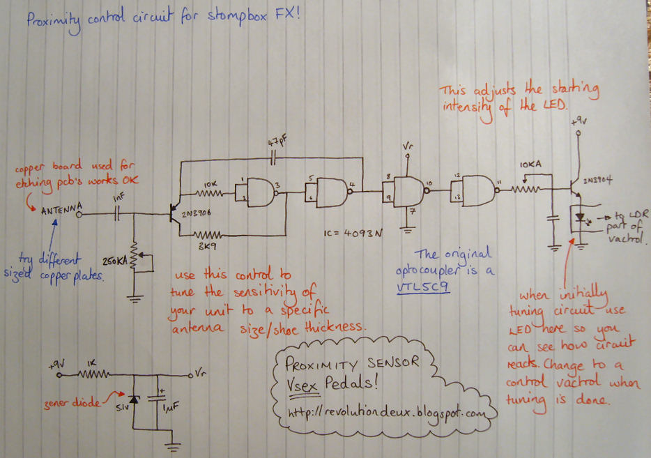
http://4.bp.blogspot.com/_y4AYtND8Hz8/R ... _probe.jpg
schematic a try.
Well, I did a layout and it works (I can post it here if someone is interested), but it is too sensitive. The LED only needs to light up when you touch the key or just before (to give some touch sensitivity, although that's not really a requirement, I am happy if it just reacts to on/off).
Does anybody have an idea how I can dampen the sensitivity somewhat? Initially I was running it at 12v, functionality improves by going to 9v, so I will probably do a re-layout to get a regulator onboard (maybe one for the reference voltage as well).
I built a Probe Wah earlier, using the "Earth and space interface" schematic, and that worked fine. This time around, I want to build a few touch pads for my modular synth. A touch keyboard so to speak.
Thought I'd give this:
http://4.bp.blogspot.com/_y4AYtND8Hz8/R ... _probe.jpg
schematic a try.
Well, I did a layout and it works (I can post it here if someone is interested), but it is too sensitive. The LED only needs to light up when you touch the key or just before (to give some touch sensitivity, although that's not really a requirement, I am happy if it just reacts to on/off).
Does anybody have an idea how I can dampen the sensitivity somewhat? Initially I was running it at 12v, functionality improves by going to 9v, so I will probably do a re-layout to get a regulator onboard (maybe one for the reference voltage as well).
"It crackles....., but that's ok"
-
Jaicen
- Breadboard Brother
Two ways I can think of to reduce the sensitivity:
1: Reduce the antennae size, or add capacitance in parallel. Both will have the effect of reducing the 'range' of the proximity sensor.
2: Lower the operating voltage; reduces effective range of controller. This is going to be trickier to dial in, and wouldn't be my preferred method.
Of course, you could just tie the output of the sensor to the gate of Jfet acting as an on/off switch, that's probably the most elegant solution.
Greetings,
Could an FET or a BJT be used instead of LDR in this type of circuit? Morley substituted the LDR by a Phototransistor in his pedals (guess due to the higher speed compared to the LDR). I plan to use a potentiometer to control the BJT or FET instead of a pot controlling an LED pointing to an LDR.
Would that be possible?
Thanks in advance.