Sorry for the improvised wooden box, this one is for testing purposes only:
I will try to give a brief description of the work of the clone I did. The pedal has been compared today with the original (ver.3 2004) and I can say that it behaves almost identically. The operation of the potentiometers is identical, the tone is identical in all positions.
Considering that I worked the PCB with the use of cheap 2n7000 aliexpress Chinese transistors, I can say that I am very satisfied.
By using original transistors and better capacitors, I think that the last glimmer of doubt will disappear.
Btw. we used two amps and two guitars:
Fender Bassman 59 (Clone) & Fender Blues Deluxe RI, and Fender Mex Telecaster & Gibson Les Paul Traditional with custom pickups!
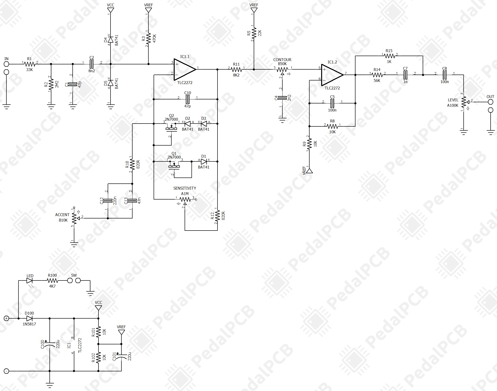
Superbly done pedal schematic. Big thanx to the @bugg for the contribution!