https://linksharing.samsungcloud.com/zqsKxAh2UXy4
Hey guys, I just built it following the schematic posted by extremist (years)earlier on the same page:) it sounds as it should. Before boxing it I decoded to try germanium diodes....it sounded quite good but with certain decrease in volume...I tried to compensate by changing R18 (according to this schematic) to 470K. Was that a good idea or you would suggest something else in order to stick with the ge diodes
Thanks for your attention!
CHEERS!
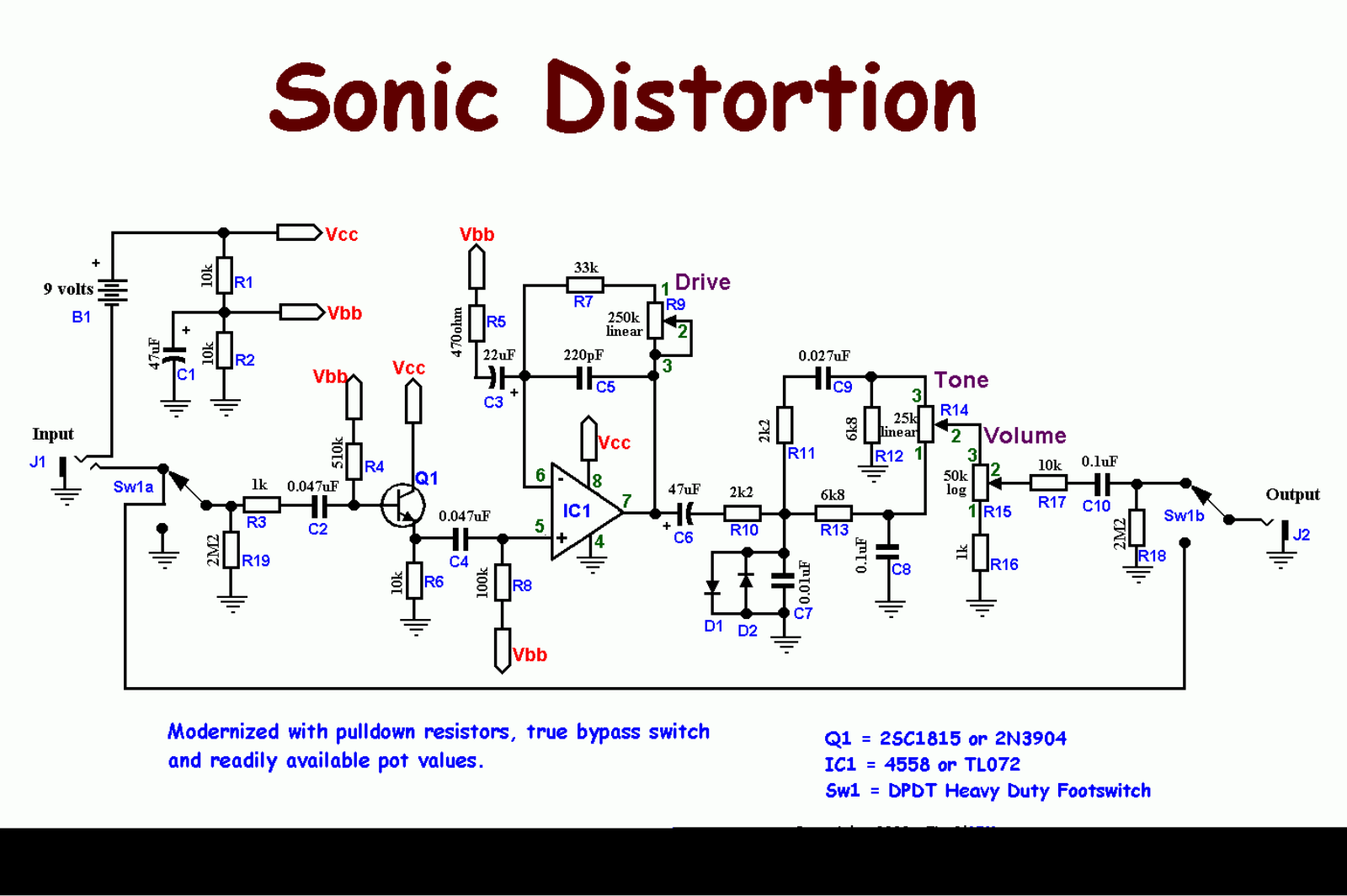
Ibanez - SD-9 Sonic Distortion [schematic]
-
CheapPedalCollector

- Resistor Ronker
Isn't going to help at all most likely, I'd repurpose the unused op-amp stage as a boost after the tone control circuit.
Thanks...would that change cause any negative impact anyway..like messing with output impedance...
-
CheapPedalCollector
- Resistor Ronker
Yes but not much.
Hi everyone,
I made this pedal following the following wiring diagram
https://manualmachine.com/html/b2/b233/ ... NHWkE.png
When the pedal is turned on, everything works and the sound is slightly distorted but the amount of gain does not change as the drive pot is rotated even if I turn the pot to maximum. I tried different pot values, the last one I tried 1M log but nothing has changed. The welds seem to me to be done well and I also checked all the connections with a multimeter and there are not even short circuits and it makes me think that the scheme is not correct. Maybe the value of some component saturating the potentiometer to a fixed value?
Thanks !!
Brian has one over on the madbean site.popstudioguitar wrote: ↑08 May 2008, 11:07 Great,
I've read that thread. A good appetizer !
Anyone have a vero layout or a PCB for it ?
I would like to compare with the GGG. Seems that a lot of things are missing on their schematic (only switching wise ??).
Thanks
hey guys...
i built this pedal based on a schematic posted by Extremist on page 4. what i do not understand is why R3 and R15 are not of the same value? with R3= 510K and R15=1M i couldnt get the same bias voltages on both transistors. i would appreciate your answers..
thanks! cheers!
i built this pedal based on a schematic posted by Extremist on page 4. what i do not understand is why R3 and R15 are not of the same value? with R3= 510K and R15=1M i couldnt get the same bias voltages on both transistors. i would appreciate your answers..
thanks! cheers!
JHS wrote: ↑10 May 2008, 08:24 All schems I saw so far don't show the O-buffer and the FET-switching, just a simplified SD-9 OD-circuit.
I recieved a redrawn factory schem, showing an early SD-9. Seems to be a transition model and maybe this redrawn schem has some errors . The first SD-9 don't have a 100uF filter cap in the BIAS divider. The cap is the RC network of the OD-circuit is a electrolytic 22uF, later SD-9 have only 0,1uF. IMHO technical the schem is correct and will work but w/o the factory schem part and value checking is impossible.
JHS
-
andregarcia57
- Cap Cooler
hello everything is fine?
Thanks for the file, I'm finishing generating a gerber file and I would like some help with the cables (wires) that are missing and in relation to the diodes they seem to be inverted
could you help me? grateful
- Attachments
-
- SD9.png (128.31 KiB) Viewed 983 times