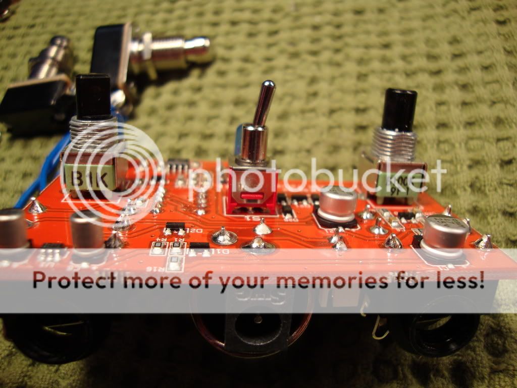
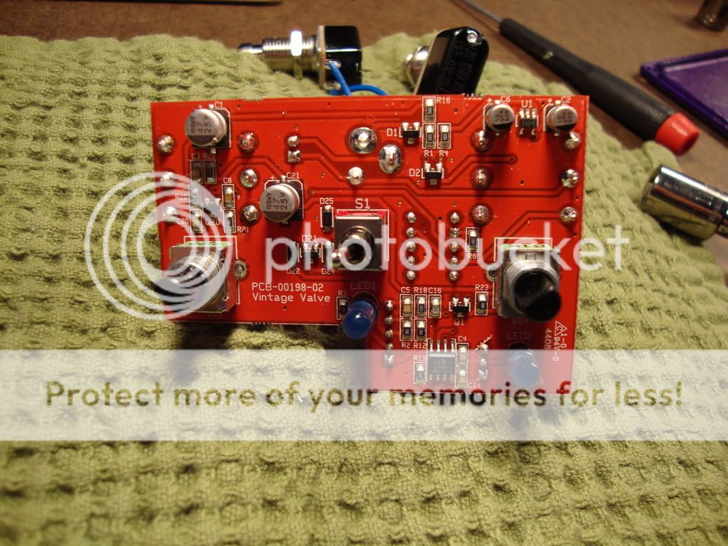
Picked this guy up and figured I'd post the guts. Got a new camera and the macro works really well. I was happy with the results. If anyone wants the original i.e. LARGER pictures, just lemme know, I'll send them to you directly. Also, if you'd like pictures from alternate angles or part values please just hollar.
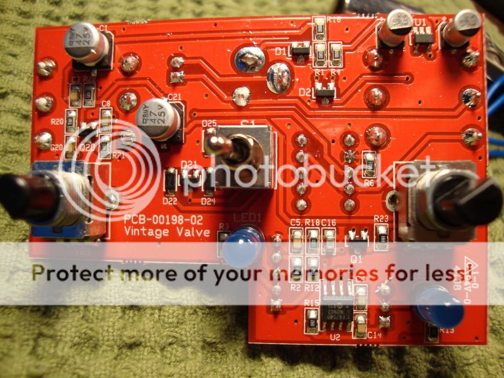
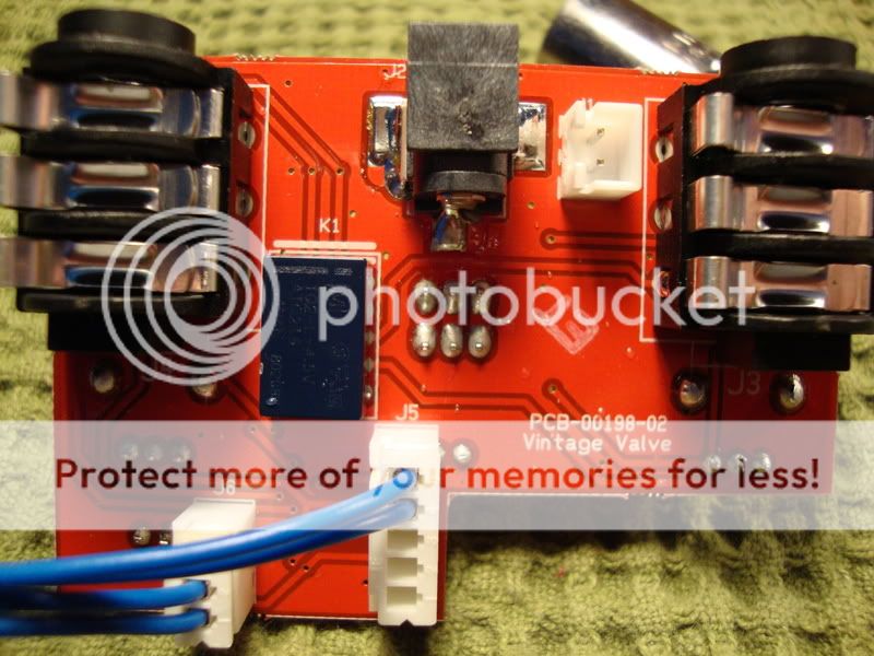
You may notice an empty connector, it's for the battery. The battery connects to the board just like the switches. Funny thing is, the switching isn't really silent. I can hear a little click when they engage. Enjoy
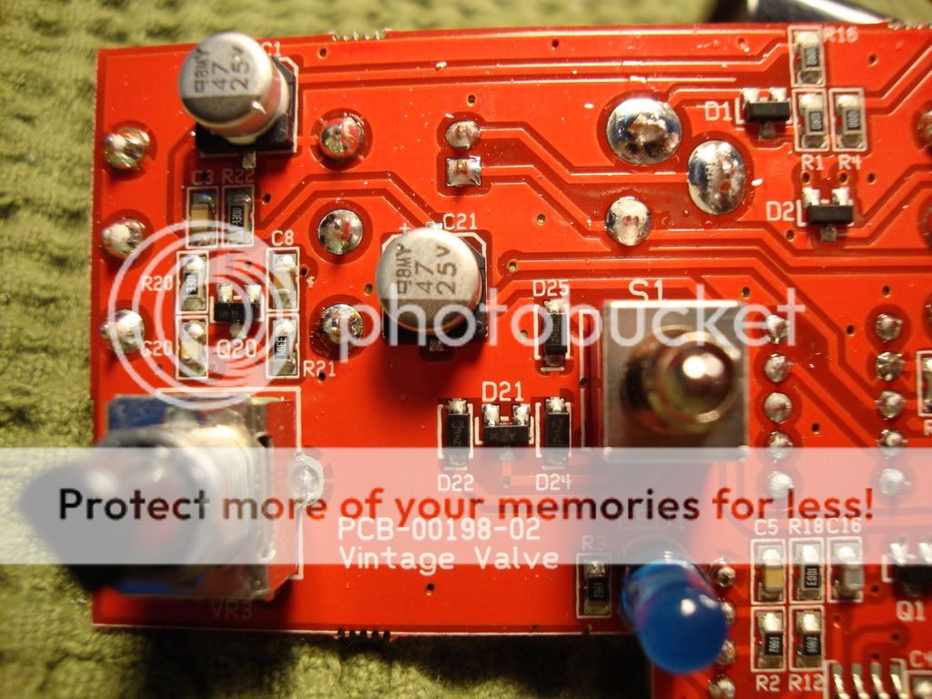
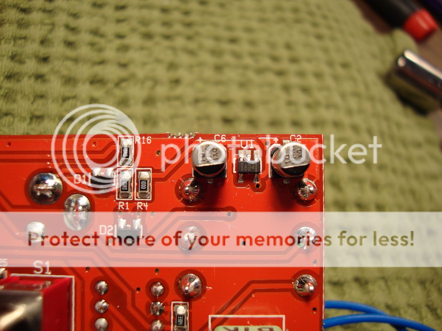
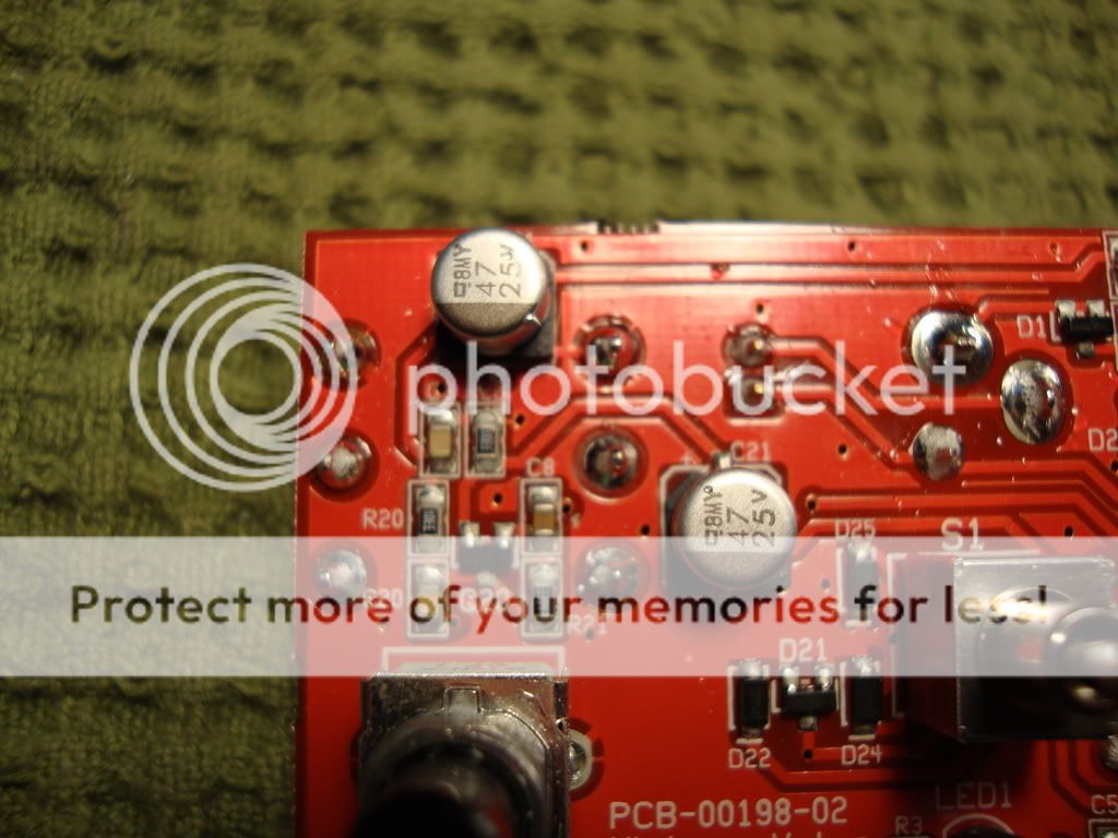
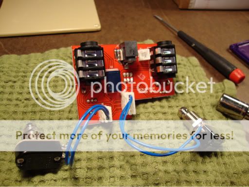
My first guess is a single transistor boost with clipping diodes. The switch changes between different diodes. Everything else is for controlling the relay.
"Analog electronics in music is dead. Analog effects pedal design is a dead art." - Fran
soulsonic wrote:Everything else is for controlling the relay.
Damn. That seems like an awful lot of components just for switching. Why the hell would you make a bypass switch so complex? If your guess is correct, then the switching is about 5x the complexity of the effect part of the circuit.
soulsonic wrote:My first guess is a single transistor boost with clipping diodes. The switch changes between different diodes. Everything else is for controlling the relay.
SMD Electra-like circuit. That was my guess as well, would be funny if that were indeed the case.
Should be able to compare the switching to Cusacks pedals. IIRC, Cusack designed the switching for Sean.
I could certainly be wrong about everything in my post though !
reveriesof wrote:ive always assumed it's the woodrow/electra mod w/ a diode switch, cos it's sposed to be a "5E3" aye?
no, it's supposed to be a supro.
"You've converted me to Cubic thinking. Where do I sign up for the newsletter? I need to learn more about how I can break free from ONEism Death Math." - Soulsonic
The relay circuit by Cusack is pretty small. Does anybody know if he does the layouts as well? I doubt Sean does much these days except count the money flowing in.
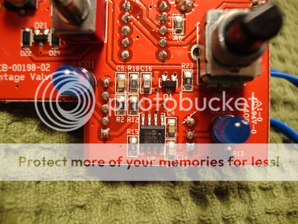
It's a Woodrow with switchable diodes. Looks like only one half of the pair is switched. Can't decipher the boost function at a quick glance, but looks like it might switch from a fixed gain setting to a variable control.
Even though the ad copy suggests that the boost activates a cascaded gain stage, I do not see the second transistor (setup) that would make this true.
What I do see is Q1 acting as, what I assume, is a VVR in series with VR4, both in parallel with the Q20's emitter resistor (330R). When the JFET's resistance is high (assume 1Meg with boost off), the affect on the 330R is very little, but when it is low (assume 1R with boost on), VR4's (variable resistor) value of 1R to 1K in parallel with the 330R increases the gain of Q20 by dropping the resistance.
WhiteKeyHole wrote:Looks like only one half of the pair is switched.
Wrong, sorry. A BAT46 pair in the 5E3 position, a BAV99 in the Tweed Twin position. In the Tchula position, a single BAT46 is put in parallel with the BAV99, for asymmetrical clipping.