mictester wrote:
I saw something similar to this yesterday, but it was a homebrew job. It was an LM386 amplifier driving into a transformer, with the usual diode doubler configuration at the output.
That part of it sounds like the old "Bob Starr Octavia" or "Bobtavia" for short. The op amp recovery stuff is different though. The bobtavia sounded good driving a distorted amp or a distortion pedal. Did a good octave but not quite enough gain on its own. Maybe that's the reason for the recovery stage on the one you saw.
EDIT: Oops! Didn't see Phibes post where he already mentioned this. Sorry...
"You have just tubescreamered or fuzzfaced yourself " -polarbearfx
John Lyons wrote:I don't see how there can only be two resistors in the octave clang.
If it's an op amp they could be running it wide open as a comparator with the 2 resistors to set the bias. Seems like the kind of thing these guys would do.
"You have just tubescreamered or fuzzfaced yourself " -polarbearfx
mictester wrote:
I saw something similar to this yesterday, but it was a homebrew job. It was an LM386 amplifier driving into a transformer, with the usual diode doubler configuration at the output.
That part of it sounds like the old "Bob Starr Octavia" or "Bobtavia" for short. The op amp recovery stuff is different though. The bobtavia sounded good driving a distorted amp or a distortion pedal. Did a good octave but not quite enough gain on its own. Maybe that's the reason for the recovery stage on the one you saw.
I did a 386 into a PNP/NPN pair (stole it from Escobedo), and it does wicked octave:
I did a simplified version sans inductor, but it doesn't sound quite as good:
Maybe those ideas will spur some thought as to the Octave Clang's workings?
John Lyons wrote:I don't see how there can only be two resistors in the octave clang.
The IC needs to be biased either with a voltage divider on the input
John Lyons wrote:I don't see how there can only be two resistors in the octave clang.
The IC needs to be biased either with a voltage divider on the input
not if it's a lm386
You're right, but In the picture it looks like the IC is an LM741.
In the last pics that John posted (the earlier model) you can get a clearer view of the IC. I have a LM741 that looks identical to the chip in the pic. Same logos etc. Also note the thickness of the pins. Pins 2,3,6, and 7 are all way thicker than the others. The LM386's I've seen don't have that. That early model is even stranger as there's only one resistor visible! It has a red LED though. I can't tell if its a mistake the way they wired the output control on that one. Its wired as a variable resistor to ground instead of a voltage divider. Not very effective as a volume control. They corrected this in the later version.
doug deeper wrote:i have a hunch there are some resistors on the back of the board.
That could be true, but I dont understand why you would go to the effort to make such a nice board like that (Three different versions from what I can tell) and on every revision leave the resistors under the board.
doug deeper wrote:i have a hunch there are some resistors on the back of the board.
That could be true, but I dont understand why you would go to the effort to make such a nice board like that (Three different versions from what I can tell) and on every revision leave the resistors under the board.
Maybe it's to throw off chancers like us!
SMT resistors on the underside saves drilling and leads to neater layouts.
I really doubt these guys are doing anything SMT. But, stranger things have happened at sea!
True enough; I mean, having seen how far their game has been stepped up from that other pedal that was shown in here, I don't think anything they could do would surprise me...
i actually built one of these, using a 386.
it has all of the trademarks: horrible sound & ridiculously high output volume. i sure liked that
thus... it might be one. also, if you buy bulks of 386s directly from asia, their looks can vary a lot.
just my 2ct...
my favorite amplifier: My Glass Hero Amplification
Completed builds: 1973 Orange Graphic 120 head Fender Champ clone head custom Pentode input single channel 20 watt head custom "plexi" 5 watt single ended head custom Pentode input single channel ~2 watt combo (smaller version of my 20watt) ( i build amps and pedals )
pedal clones Pro Co Rat Univox SuperFuzz Sonic Edge J&J Overdrive Interfax Harmonic Percolator EHX Electric Mistress EHX Big Muff PI EHX Big Muff into a DBA Fuzz War Green Ringer Orange Squeeze Boss Slow Gear Death By Audio Sound SAW Death By Audio Armageddon Death By Audio Fuzz War MXR Phase 90 EA Tremolo TS 808 another TS808 modded out for bass various loop, boost, kill, stutter, feedback and signal pad stompboxes
pedal modds big muff clipping modds and internal feedback loops w/ LDRs EHX POG exp pedal modd VOX 847 wah modds (expression pedals should be expressive) Cry Baby Modds BOSS XT-2 modds
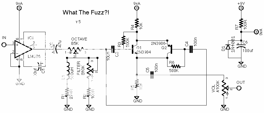
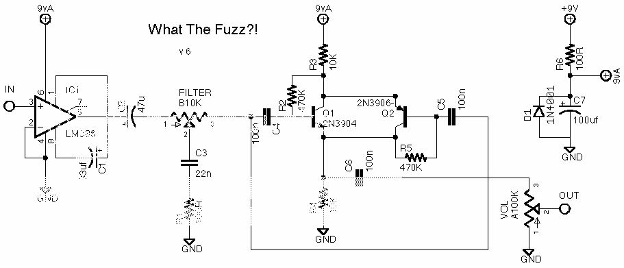
i'm bringing this back from the dead because i have a schem for this.. i got to peak inside an octave clang the other day and it only took about 25 mins to come up with this..
Its much like a bobtavia.. the transformer is a 2k secondary and 10k primary..and you drive the secondary and take the out from the primary.. the input filter is much like the supersonic fuzz gun density control.. pin 5 is grounded, this is part of the null offset on the lm741.. pins 1,3,8 are left open.. i did not add the switching or LED in the schematic..
Glass_Hero wrote:i'm bringing this back from the dead because i have a schem for this.. i got to peak inside an octave clang the other day and it only took about 25 mins to come up with this..
Its much like a bobtavia.. the transformer is a 2k secondary and 10k primary..and you drive the secondary and take the out from the primary.. the input filter is much like the supersonic fuzz gun density control.. pin 5 is grounded, this is part of the null offset on the lm741.. pins 1,3,8 are left open.. i did not add the switching or LED in the schematic..
Just great! This will be my next build, just a couple of questions....
1. Is this scheme sure to work?
2. What hapens if you switch the values of the transformer? Seems quite hard to find the exact values in my part of the world. Also is the middle-left leg of the transformer left open?
3.Is the symbol at pin 7 only the 9 V DC input? And which pin is pin 8?