This has been discussed but there is no definitive schematic here.
The theories are that it's either an Octavia or Bobtavia rework.
Anyone have one for study?
Death by Audio - Octave Clang [traced]
-
John Lyons

- Solder Soldier
-
John Lyons
- Solder Soldier
Ok, cool... thanks.
Obviously not an Octavia clone.
Obviously not an Octavia clone.
-
Steven_M

- Resistor Ronker
Interesting. I think that must be a new version. The guitarist in my old band had one (No DC jack) and when I opened it to put a battery inside I remember the Germanium diodes and the transformer, but I remember transistors, not an opamp. Also the pcb was longer.John Lyons wrote:Ok, cool... thanks.
Obviously not an Octavia clone.
I'll see if I can ask him to take some pictures inside for us.
-
Steven_M
- Resistor Ronker
http://www.guitariste.com/forums/pedale ... 24,20.html
Octave clang on this site with a slightly different layout
The version that I played with was this smaller box version:
Octave clang on this site with a slightly different layout
- octaveclang.gif (3.33 KiB) Viewed 7753 times
-
devastator

- Cap Cooler
I think there's something like this on aron's forum, a AOP booster in front of a transformer with diodes, basically like an octavia. Nothing original here .
-
mictester

- Old Solderhand
Information
I saw something similar to this yesterday, but it was a homebrew job. It was an LM386 amplifier driving into a transformer, with the usual diode doubler configuration at the output. It had a simple passive tone control network after the diodes, and an op-amp gain recovery stage, with the second half of the dual op-amp used for the bypassed audio. It sounded just like an Octavia, and was built by some bloke in Berkhamstead, Hertfordshire (I remember the address inside it), and was a pretty good quality build.devastator wrote:I think there's something like this on aron's forum, a AOP booster in front of a transformer with diodes, basically like an octavia. Nothing original here .
"Why is it humming?" "Because it doesn't know the words!"
-
phibes

- Transistor Tuner
Information
I had the same thoughts come to mind as Mictestor. Google Bobtavia or Bob's Octavia. Should be pretty similar.
GuitarlCarl - "TGP = The Gear Polishers"
 Ken
Ken
Ken
-
Solidhex
- Resistor Ronker
The closest thing I've seen to it is this Gus Smalley "Simple Octave Up" circuit 
The Octave Clang though as far as I could tell has an input cap blend going straight into pin 2 of a LM741 (thanks to John for spotting the chip type for me). Judging from the amount of fuzz going on in the clips I've seen I'm guessing the gain control to be maybe a 1meg in series with that 82k going from the output pin 6 back to pin 2. Pin 3 unconnected? The electro cap ( 22uf? ) goes from pin 6 to the transformer which is set up like an octavia. Germanium diodes. Output volume control. I'm not sure what the 470k resistor's role is. I've tried it connected from pin 2 to ground. I think at least one end of it is connected to ground just from its vicinity to pin 4 of the IC. I've breadboarded it and it sounds very close to the samples. Unfortunately its noisy as hell and sounds like weird radio frequencies when the gain control is turned. Shouldn't be super hard to figure out with such a low parts count...
The Octave Clang though as far as I could tell has an input cap blend going straight into pin 2 of a LM741 (thanks to John for spotting the chip type for me). Judging from the amount of fuzz going on in the clips I've seen I'm guessing the gain control to be maybe a 1meg in series with that 82k going from the output pin 6 back to pin 2. Pin 3 unconnected? The electro cap ( 22uf? ) goes from pin 6 to the transformer which is set up like an octavia. Germanium diodes. Output volume control. I'm not sure what the 470k resistor's role is. I've tried it connected from pin 2 to ground. I think at least one end of it is connected to ground just from its vicinity to pin 4 of the IC. I've breadboarded it and it sounds very close to the samples. Unfortunately its noisy as hell and sounds like weird radio frequencies when the gain control is turned. Shouldn't be super hard to figure out with such a low parts count...
-
Steven_M
- Resistor Ronker
This pedal is ridiculously loud. To the point that I couldn't use it! With the volume on the pedal at a hair over zero the output of this thing felt like 10 times louder than the amp. Which sucks for playing live.Solidhex wrote:The closest thing I've seen to it is this Gus Smalley "Simple Octave Up" circuit
The Octave Clang though as far as I could tell has an input cap blend going straight into pin 2 of a LM741 (thanks to John for spotting the chip type for me). Judging from the amount of fuzz going on in the clips I've seen I'm guessing the gain control to be maybe a 1meg in series with that 82k going from the output pin 6 back to pin 2. Pin 3 unconnected? The electro cap ( 22uf? ) goes from pin 6 to the transformer which is set up like an octavia. Germanium diodes. Output volume control. I'm not sure what the 470k resistor's role is. I've tried it connected from pin 2 to ground. I think at least one end of it is connected to ground just from its vicinity to pin 4 of the IC. I've breadboarded it and it sounds very close to the samples. Unfortunately its noisy as hell and sounds like weird radio frequencies when the gain control is turned. Shouldn't be super hard to figure out with such a low parts count...
-
John Lyons
- Solder Soldier
I don't see how there can only be two resistors in the octave clang.
The IC needs to be biased either with a voltage divider on the input
as in Gus's simple octave up or with a voltage divider and a series
resistor which sets the impedance. Example: 2 10Ks in series from +
to ground with the voltage reference taken from the junction of the two
with a 470kish resistor in series to the input of the IC.
Either of these use at least two resistors if not 3.
So what about the other resistors in the circuits mentioned?
Brad
Did you breadboard Gus's just as it's drawn?
I know it's not the same as the Octave Clang but...
Sub in a 1M for the 50K pot.
Usually you only want 10K or less from the negative input
of the IC to ground (or Vref)
There should be a cap across the feedback pat as well.
100pf or so. That would quell oscillation (maybe what you've got going)
We need an octave clang to peek at!
-
Steven_M
- Resistor Ronker
I dont think this pedal company is known for having circuits that are theoretically accurate. . But having said that, is one of the pots acting as that third resistor you mention?John Lyons wrote:I don't see how there can only be two resistors in the octave clang.
The IC needs to be biased either with a voltage divider on the input
as in Gus's simple octave up or with a voltage divider and a series
resistor which sets the impedance. Example: 2 10Ks in series from +
to ground with the voltage reference taken from the junction of the two
with a 470kish resistor in series to the input of the IC.
Either of these use at least two resistors if not 3.
So what about the other resistors in the circuits mentioned?
Brad
Did you breadboard Gus's just as it's drawn?
I know it's not the same as the Octave Clang but...
Sub in a 1M for the 50K pot.
Usually you only want 10K or less from the negative input
of the IC to ground (or Vref)
There should be a cap across the feedback pat as well.
100pf or so. That would quell oscillation (maybe what you've got going)
We need an octave clang to peek at!
-
Hides-His-Eyes

- Tube Twister
I suppose one of the pots could be setting the bias, but that seems pretty odd to me.
Testing, testing, won too fwee
-
DrNomis

- Old Solderhand
Information
- Posts: 6807
- Joined: 16 Jul 2009, 04:56
- my favorite amplifier: Self-Built Valve Amp Head :)
- Completed builds: Dallas Arbiter Fuzz Face,Tone Bender Professional Mk 3,Tone Bender 3-Knob,Baja BK Butler Tube Driver,Baja Real Tube Overdrive,Roger Mayer Octavia,EH Soul Preacher,Tech 21 XXL Distortion,MFOS Weird Sound Generator.
- Location: Darwin,Northern Territory Australia
- Has thanked: 98 times
- Been thanked: 279 times
Hides-His-Eyes wrote:I suppose one of the pots could be setting the bias, but that seems pretty odd to me.
It looks to me that one of the pots is controlling the gain of the op-amp IC,the other pot is just an output control....
Genius is not all about 99% perspiration, and 1% inspiration - sometimes the solution is staring you right in the face.-Frequencycentral.
-
Hides-His-Eyes
- Tube Twister
And there are 3 of them... I guess it's a 'fuzz' control though.
He wouldn't set one pot as BOTH R_a and R_b of the op-amp would he?
He wouldn't set one pot as BOTH R_a and R_b of the op-amp would he?
Testing, testing, won too fwee
-
DrNomis
- Old Solderhand
Information
- Posts: 6807
- Joined: 16 Jul 2009, 04:56
- my favorite amplifier: Self-Built Valve Amp Head :)
- Completed builds: Dallas Arbiter Fuzz Face,Tone Bender Professional Mk 3,Tone Bender 3-Knob,Baja BK Butler Tube Driver,Baja Real Tube Overdrive,Roger Mayer Octavia,EH Soul Preacher,Tech 21 XXL Distortion,MFOS Weird Sound Generator.
- Location: Darwin,Northern Territory Australia
- Has thanked: 98 times
- Been thanked: 279 times
Hides-His-Eyes wrote:And there are 3 of them... I guess it's a 'fuzz' control though.
He wouldn't set one pot as BOTH R_a and R_b of the op-amp would he?
I don't think he would,I'm assuming that R_a refers to the fixed 100 Ohm resistor,and R_b is the 100k pot in the schematic,if so,then there wouldn't be any advantage to making R_a variable,most likely the third pot is configured as a high-cut tone control,my theory anyway,but I could be totally wrong about that...
Incidentaly,I can only see two pots in the schematics he posted....
I've got an Octavia pedal that I made from a Roger Mayer Schematic,which I think from memory,was drawn by R.G. Keen,the schematic specified MPSA18 for three of the transistors,I couldn't buy any MPSA18 transistors anywhere,but I was able to buy some MPSA14 transistors,so I used them in my pedal build,and it worked fine,do you think any freestompboxes members would be interested in me posting some pics of it?....
Genius is not all about 99% perspiration, and 1% inspiration - sometimes the solution is staring you right in the face.-Frequencycentral.
-
John Lyons
- Solder Soldier
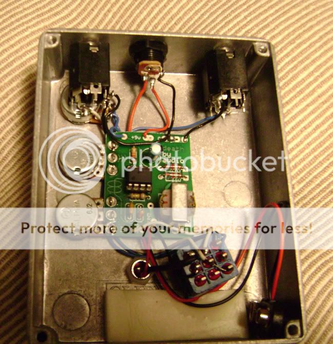
I think one pot is "fuzz" via 1M resistance in the feedback loop as mentioned.
One knob is a tone control (blend as mentioned possibly) and the third pot is
is volume (all on the Octave clang).
I just don't know how the op amp is biased without at least two resistors.
Some pics to confuse the issue even further.


One knob is a tone control (blend as mentioned possibly) and the third pot is
is volume (all on the Octave clang).
I just don't know how the op amp is biased without at least two resistors.
Some pics to confuse the issue even further.
Last edited by John Lyons on 12 Nov 2010, 04:37, edited 1 time in total.
-
DrNomis
- Old Solderhand
Information
- Posts: 6807
- Joined: 16 Jul 2009, 04:56
- my favorite amplifier: Self-Built Valve Amp Head :)
- Completed builds: Dallas Arbiter Fuzz Face,Tone Bender Professional Mk 3,Tone Bender 3-Knob,Baja BK Butler Tube Driver,Baja Real Tube Overdrive,Roger Mayer Octavia,EH Soul Preacher,Tech 21 XXL Distortion,MFOS Weird Sound Generator.
- Location: Darwin,Northern Territory Australia
- Has thanked: 98 times
- Been thanked: 279 times
John Lyons wrote:I think one pot is "fuzz" via 1M resistance in the feedback loop as mentioned.
One knob is a tone control (blend as mentioned possibly) and the third pot is
is volume (all on the Octave clang).
I just don't know how the op amp is biased without at least two resistors.
That's the usual way of biasing an Opamp if it is powered by a single supply rail,but some opamp circuits are powered from a dual supply rail system,usually the non-inverting (+) input is tied to circuit ground and the opamp output sits at 0V,but on a single supply rail,the two equal value resistors are used to generate a 1/2Vsupp bias voltage for the opamp-s inputs,the output will sit at the 1/2 Vsupp voltage....
Genius is not all about 99% perspiration, and 1% inspiration - sometimes the solution is staring you right in the face.-Frequencycentral.
-
John Lyons
- Solder Soldier
I follow you, but with a dual supply you either need a charge pump +/-
supply or dual batteries and this isn't the case here.
supply or dual batteries and this isn't the case here.