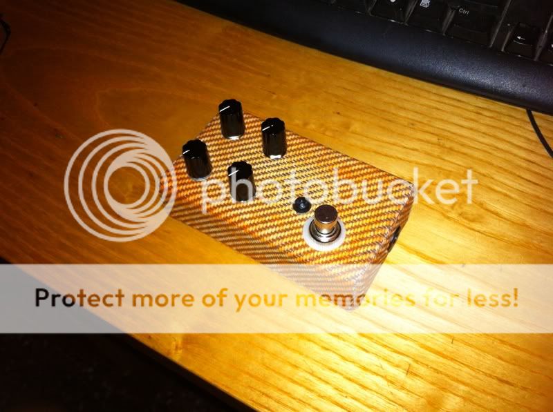
I love that he marked that outMoustache_Bash wrote:Some poopy pictures...
Top
Bottom
IC underneath the electrolytic is a TL072CN, and the IC underneath the film cap is marker'd out.
Mid-Fi Electronics - Pitch Pirate - Guts, Schematic [traced]
- rousejeremy
- Breadboard Brother
Information
Any vero for this yet? Pretty please?
- doug deeper
- Breadboard Brother
It's a 386. I was thinking of you guys when I did this! I never cross stuff out but when ever I do something like this as a joke to myself it ends up here! 
- Beedoola
- Resistor Ronker
that a trimmer going to the input of the 386? I've built a PPirate before and found I got some clipping if I dug into my guitar, does the trimmer help with that?
- doug deeper
- Breadboard Brother
It's a trimmer.
These have low headroom, it's intentional!!!
That's why I black out ICs. Protect my mojo secrets.
Brain property. l
l
These have low headroom, it's intentional!!!
That's why I black out ICs. Protect my mojo secrets.
Brain property.
second for a vero.
pretty please?
pretty please?
Here is a vero layout that works well for me. It's from the Madbean schematic so it's not the deluxe version but it does sound just like the original You Tube demos. I'm not sure of the correct taper for the pots but log for the depth pot and linear for the others seems to work well. I tried a few LDR's and they all worked to some extent. However I got some great results with the Silonex NSL 4962 (available for Farnell amongst other places). I should say that I copied this layout from a paper version (I'm new to DIYLC) so it has not been directly verified (although I have checked it over a few times.......).
Anyone verify this?
I built it. It works although it does not get quite as crazy as the original. Im using a vtl5c3.
- Beedoola
- Resistor Ronker
I didn't build one using this layout but I did build others using FXgod's layout in previous pages as well as just doing a perf build. I used the linked below photocell and a 5mm waterclear White LED.OnTheTundra wrote:I built it. It works although it does not get quite as crazy as the original. Im using a vtl5c3.
http://www.smallbearelec.com/servlet/Detail?no=1003
I don't know about vactrols (I didn't try one) but you can get a very strong effect if you are prepared to mess around with the ldr/led. I originally used a bright white led but the effect was actually too bonkers for me so I swapped it for a bright blue and this was more controllable. As I understand it, the spectral peak of the ldr (CdS) should be about 520 nm (should be bang on for bright green) but I read somewhere that this can vary by +/- 50 nm, hence the need to play around with the led.OnTheTundra wrote:I built it. It works although it does not get quite as crazy as the original. Im using a vtl5c3.
I took the vactrol out and messed around with the led/ldr and Im happy with it now. Id call that layout verified but it looks like it could be shaved down a bit. Maybe I'll have a crack at it and post my layout this weekend.
- elrengofa
- Breadboard Brother
well, here are my files for this circuit, in the rar you can find schematic, layout and pcb in pdf format ready to etch. Also have the eagle files to modify something if you want.
Greetings form Argentina
Greetings form Argentina
- Attachments
-
 pitch pirate.rar
- (98.23 KiB) Downloaded 441 times
- rasta_maleek
- Resistor Ronker
a photo of my unit tuned.


- rasta_maleek
- Resistor Ronker
hi friend.Moustache_Bash wrote:Some poopy pictures...
Top
Bottom
IC underneath the electrolytic is a TL072CN, and the IC underneath the film cap is marker'd out.
Bottom
Top
Hidden behind the wires,
Don't really know how you all go about solving pedals, but all I've ID'd so far is the ICs and caps (5-47uf, 8-0.1uf, 1-.01uf, 1-1uf, and 2-.001uf). I'll keep trying to make out all the components, if anybody cares.
have you got the pot values of the deluxe version, i would make a clon.
cheers
- Nocentelli
- Tube Twister
Information
- Posts: 2222
- Joined: 09 Apr 2009, 07:06
- Location: Leeds, UK
- Has thanked: 1155 times
- Been thanked: 954 times
Check your regulator pinout - You might have it reversed,
modman wrote: ↑ Let's hope it's not a hit, because soldering up the same pedal everyday, is a sad life. It's that same ole devilish double bind again...


