You are right for the tone pot is a 25 k linear, wired in order that clockwise the "tone1" is decreasing in value.
And you are right, the final 100k resistor is just to simulate a volume pot at the maximum value.
I simulated it in LTspice and did not feel like redoing the whole schematic in another program. I just assume some of the readers will have enough knowledge in electronics to figure our what it means (it is not exactly a "complex" circuit...).
If someone want to redraw it, please go on and I will check for any discrepancy.
Wampler - Ecstasy [traced]
-
IvIark

- Tube Twister
Information
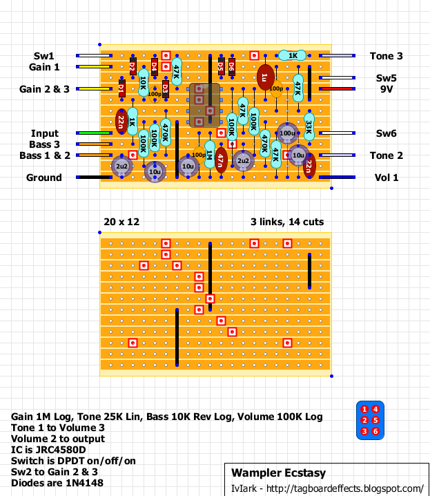
Cool, cheers for the info. Here's the vero:
"If anyone is a 'genius' for putting jacks in such a pedal in the only spot where they could physically fit, then I assume I too am a genius for correctly inserting my legs into my pants this morning." - candletears7 - TGP
-
jymaze
- Resistor Ronker
Hello,
Still no build for this one? I was wishing for some feedback on how it sounds.
I redid the schematic in TinyCAD because the first versions I did look seriously bad. Maybe it will be stimulating enough for someone to build it.
There are 3 voltage dividing networks in the original circuit, but only one would be fine. It is clearly overkill.
Here it is:
- Attachments
-
 Ecstasy.pdf
- (14.69 KiB) Downloaded 1675 times
-
IvIark
- Tube Twister
Information
Someone built it on my blog and loves it, so it appears that everything is good. Check out this thread and if you look a bit further down you'll see a sound sample he did on bass.
http://www.talkbass.com/forum/f36/overd ... st12906324
http://www.talkbass.com/forum/f36/overd ... st12906324
"If anyone is a 'genius' for putting jacks in such a pedal in the only spot where they could physically fit, then I assume I too am a genius for correctly inserting my legs into my pants this morning." - candletears7 - TGP
JYMaze
I have built the vero layout from IVIark. It is a great sounding pedal. I find that I have to keep the tone control around the last 10% of the sweep. Anything below 5'oclock and its just muffled and bassy. I used your mods for the tone control on my Riot build and it made it a different pedal. Too dark before - perfect after the mods.
I was wondering how to voice the tone circuit on the Ecstasy to have a more treble available and to be able to use more of the pot sweep. I assume the 22n cap is a place to start. Any suggestions? Hope I explained what I am experiencing clearly enough.
Thanks
-
jymaze
- Resistor Ronker
Tinkercreek,
Effectively, I would start by socketing the tone cap. Then probably switching to a 10n instead of a 22n can suit your needs. Also, make sure you used a linear pot for the tone control and not a log.
Good luck!
Effectively, I would start by socketing the tone cap. Then probably switching to a 10n instead of a 22n can suit your needs. Also, make sure you used a linear pot for the tone control and not a log.
Good luck!
JYMaze
I will try those things this weekend when I have time to dig into it. It really is a great sounding pedal and covers a lot of sonic territory with the diode switching. I look forward to just giving it a little tweak. Thank you for the quick reply.
Let me thank you again for the Riot tone mods. I was getting ready to gut the pedal and reuse the enclosure when I thought I would read the whole post here for ideas. After the mods it is really opened it up and made it a usable high gainer. One of my favorites. Owe you big time!!
-
jymaze
- Resistor Ronker
Hey,
I am glad you liked my Riot tone mods. I hope a lot of people tried it since it really transforms this pedal into something much more usable.
Also, I read my post again and thought about it a little better:
Actually, in your case, if you'd like the tone pot to have more usable range in the bright settings, you SHOULD try a log instead of a linear pot.
But you should just try the cap mod first since it may be just enough for your taste.
Sorry for the confusion.
Hey man
Yeah. As it is right now, I can get what I need tone-wise, but I only have about a quarter inch of sweep where I can adjust for the sweet spot. I think that your suggestions will give me a little more adjustment area on the pot, as well as more treble in the control. I usually play Strats, but I have a couple of humbucker equipped guitars that require a little more brightening up on the pedal, and right now i have to max the tone control for the humbuckers.
Appreciate the help. I'll report back after I do the mods. Hopefully it will help the next person down the line...
Thanks
JYMaze
I just got into the pedal and installed a socket for that 22n tone cap. Tried subbing a 10n first. Better than before - added a little more range and treble for the tone control. Just out of curiosity, I tried a 6.8n. It gave me a little more high end, but I found the last bit of it got just a little too brittle for my taste ( and my single coils ). Might be ok with humbuckers. Pretty happy with the 10n though. I don't have a log pot in that value laying around so I may swap that after I order a couple. That may give me more of an operable sweep - I still have to keep it near the end of the sweep with the linear pot, but its much better than before.
I may even put in a switch for those two cap values ( 10n and 6.8n ) just to have more options in the next build.
Thanks for the help! Got a better pedal and learned some tweaking in the process. One last question, if there is a somewhat easy answer: In this tone control scenario, does keeping the cap the same, and altering the value of the pot affect the tonal options in a similar fashion?
Thanks again!
-
jymaze
- Resistor Ronker
Yes, same change in the adjustable range if you divide the cap by two or the pot by two, the important thing is the product of R x C, so you can alter it as you see fit. It is just more logical to start by changing the cap to adjust the range since caps are cheaper and come in a better variety of values.
Here is a full strategy for tone adjustment for this type of circuits (simple RC filters):
1) Adjust the cap to set how dark the tone can get (bigger cap equals darker potential tone when tone pot fully turned toward bass), too dark creates some useless pot sector like you experienced.
2) Adjust the resistor before the pot (here it was set at 1k) to set how brittle the tone can get (bigger resistor limits the brittleness when tone pot fully turned toward treble), it really depends on how much treble the circuit produces.
3) If needed, alter the law of your pot for an optimal usable range.
So in your case, if you feel the 10n gives you too much high end, I would cut some brittleness by bumping the 1k resistor just before the tone pot to 2.2k. It should make it perfect!
That is a great explanation! Actually it was the 6.8n that gave me too much of the spiky treble. So the 6.8n plus the 2.2k resistor may be the optimal place. Instead of torturing this poor pedal again, I'm just going to build a second one and socket the cap and the resistor so I can play with the values.
I appreciate your patience in answering all my questions. I learn something new with each build - this is my 18th build, so I'm slowly getting there. THANK YOU!!!
I appreciate your patience in answering all my questions. I learn something new with each build - this is my 18th build, so I'm slowly getting there. THANK YOU!!!
Thank you for a vero layout.
I've made it, but my wampler seems like having the max gain in the zero "gain" pot position and only more and more as I'me turning the gain up (a very, very big amounts of gain).
If anybody had a similar problem or knows what it cold be, i would appreciate your help:)
I've made it, but my wampler seems like having the max gain in the zero "gain" pot position and only more and more as I'me turning the gain up (a very, very big amounts of gain).
If anybody had a similar problem or knows what it cold be, i would appreciate your help:)
-
rocklander

- Old Solderhand
Information
- Posts: 2726
- Joined: 18 Apr 2008, 11:33
- my favorite amplifier: my jansen bassman 50
- Completed builds: rebote 2.5; supreaux; odie; heartthrob tremolo; ross phaser; dr. boogey; thor; baja black toast; slow gear attack, rebote, tri-vibe, small clone, little angel, magnus modulus, echo base, hex fuzz, big muff, 22/7.
- Location: Rotorua, New Zealand
- Has thanked: 1406 times
- Been thanked: 231 times
- Contact:
apologies for potentially dumb question, but I don't want to assume anything.. is the switching between:R12 and D1 ... D6 and C4(gain/R1 etc)jymaze wrote:Here it is again, corrected:
world's greatest tautologist ...in the world
Ronsonic wrote:...the lower the stakes the more vicious the combat.
atreidesheir wrote:He should be punched in the vagina.
-
jymaze
- Resistor Ronker
It is a DPDT switch and one pole switches the diodes to ground while the other pole switches the diodes in the feedback loop of the opamp. I has to be wired so position 1 of the switch is diode to ground on and feed back diodes off, position 2 is no diodes at all, and position 3 is diodes to ground off and feedback diodes on.
I hope it is clear enough.
I hope it is clear enough.
-
rocklander
- Old Solderhand
Information
- Posts: 2726
- Joined: 18 Apr 2008, 11:33
- my favorite amplifier: my jansen bassman 50
- Completed builds: rebote 2.5; supreaux; odie; heartthrob tremolo; ross phaser; dr. boogey; thor; baja black toast; slow gear attack, rebote, tri-vibe, small clone, little angel, magnus modulus, echo base, hex fuzz, big muff, 22/7.
- Location: Rotorua, New Zealand
- Has thanked: 1406 times
- Been thanked: 231 times
- Contact:
thanks..jymaze wrote:It is a DPDT switch and one pole switches the diodes to ground while the other pole switches the diodes in the feedback loop of the opamp. I has to be wired so position 1 of the switch is diode to ground on and feed back diodes off, position 2 is no diodes at all, and position 3 is diodes to ground off and feedback diodes on.
I hope it is clear enough.
so "no diodes at all" means both diodes are switched to ground, or there is just open circuit between R1/d6 and R12/D1? (and are thost the right places.. I mean the correct component points)?
world's greatest tautologist ...in the world
Ronsonic wrote:...the lower the stakes the more vicious the combat.
atreidesheir wrote:He should be punched in the vagina.
-
Nocentelli

- Tube Twister
Information
- Posts: 2222
- Joined: 09 Apr 2009, 07:06
- Location: Leeds, UK
- Has thanked: 1155 times
- Been thanked: 954 times
With an on-off-on DPDT, one position (let's assume "up") connects the clipping diodes in the feedback loop for soft clipping, "down" would connect the second pair of diodes to ground for hard clipping (and disconnect the FB loop diodes), therefore the centre position disconnects both sets of diodes for a big boost with the only clipping achieved from within the opamps themselves.... I think.
modman wrote: ↑ Let's hope it's not a hit, because soldering up the same pedal everyday, is a sad life. It's that same ole devilish double bind again...
-
rocklander
- Old Solderhand
Information
- Posts: 2726
- Joined: 18 Apr 2008, 11:33
- my favorite amplifier: my jansen bassman 50
- Completed builds: rebote 2.5; supreaux; odie; heartthrob tremolo; ross phaser; dr. boogey; thor; baja black toast; slow gear attack, rebote, tri-vibe, small clone, little angel, magnus modulus, echo base, hex fuzz, big muff, 22/7.
- Location: Rotorua, New Zealand
- Has thanked: 1406 times
- Been thanked: 231 times
- Contact:
I never thought I'd say this but I think I really need to see this in the schem.. I'm confused as hell now 

or even a wiring diagram
or even a wiring diagram
world's greatest tautologist ...in the world
Ronsonic wrote:...the lower the stakes the more vicious the combat.
atreidesheir wrote:He should be punched in the vagina.
-
IvIark
- Tube Twister
Information
If you think of the switch like this:
1---4
2---5
3---6
With the top contacts made (1&2 and 4&5 cconnected) the feedback loop diodes connection is completed.
With the bottom contacts made (2&3 and 5&6 cconnected) the shunt diodes connection to vbias is completed
In the centre off position, both sets of diodes remain out of circuit.
1---4
2---5
3---6
With the top contacts made (1&2 and 4&5 cconnected) the feedback loop diodes connection is completed.
With the bottom contacts made (2&3 and 5&6 cconnected) the shunt diodes connection to vbias is completed
In the centre off position, both sets of diodes remain out of circuit.
"If anyone is a 'genius' for putting jacks in such a pedal in the only spot where they could physically fit, then I assume I too am a genius for correctly inserting my legs into my pants this morning." - candletears7 - TGP
-
Nocentelli
- Tube Twister
Information
- Posts: 2222
- Joined: 09 Apr 2009, 07:06
- Location: Leeds, UK
- Has thanked: 1155 times
- Been thanked: 954 times
My faultrocklander wrote:.. I'm confused as hell now
The second pair of diodes clips to 1/2 supply, not ground.
modman wrote: ↑ Let's hope it's not a hit, because soldering up the same pedal everyday, is a sad life. It's that same ole devilish double bind again...