Catalinbread - Naga Viper [traced]
I've built the Naga Viper with the circuit from Mark here:

It's working great, I've swapped the 500k range pot for a 100KB which suits me better.
I'm using a breadboard with a Millenium bypass (2) switch to test circuits and the strange thing I noticed is that after switching off the Naga Viper (which I connected on the breadboard for input/output/9v/grnd only) the led light of the MB board lights again after about 1 second. It remains lid.
So in bypass mode somehow the mosfet is not switching correctly? I've never seen this with other circuits.
What might be causing this?
Tx!
Hi,
I think it has to do with the fact, that the Circuit(at least following the layout) has no pulldown resistance on the output capacitor. So when your circuit is in bypass the MB2 still sees the charge in the output capacitor.
p.eat
I think it has to do with the fact, that the Circuit(at least following the layout) has no pulldown resistance on the output capacitor. So when your circuit is in bypass the MB2 still sees the charge in the output capacitor.
p.eat
Thanks! That indeed seemed to cure it.p.eat wrote:Hi,
I think it has to do with the fact, that the Circuit(at least following the layout) has no pulldown resistance on the output capacitor. So when your circuit is in bypass the MB2 still sees the charge in the output capacitor.
p.eat
Placed a 1M resistor over output to ground and the led goes off. So how does that work in simple terms.
I used this layout and it works great. I like the sound better than my original Viper.harmaes wrote:I've built the Naga Viper with the circuit from Mark here:
It's working great, I've swapped the 500k range pot for a 100KB which suits me better.
I'm using a breadboard with a Millenium bypass (2) switch to test circuits and the strange thing I noticed is that after switching off the Naga Viper (which I connected on the breadboard for input/output/9v/grnd only) the led light of the MB board lights again after about 1 second. It remains lid.
So in bypass mode somehow the mosfet is not switching correctly? I've never seen this with other circuits.
What might be causing this?
Tx!
Didn't have a 68n cap so I wired two 33s in parallel and I replaced the 40uf with a 47uf.


And hooked up to my handy dandy test box. Lets me test the circuit before I box it up. Makes troubleshooting a million times easier.

Time to order a nice shiny enclosure from Pedal Parts Plus.
-
jimosity

- Breadboard Brother
I built this from the vero layout and it has a very thin (in a bad way) tone.
Instead of using the 40uF, I used 47uF but I wouldn't assume that would cause the issue.
edit: Instead of a 68nF, the closest I had was a 57nF as well..
I've gone over it a couple times and continuity tested to make sure there were no solder bridges, all checks out fine.
I've tried a TO-18 and TO-92 package 2n222a.
What else can I be missing ?
Two of the controls work in reverse which leads me to believe that something is wired backward, but I've tried switching 1&2 to 2&3 on one of the pots and 2&3 to 1&2 to the other - didn't really help.
-
Nocentelli

- Tube Twister
Information
- Posts: 2222
- Joined: 09 Apr 2009, 07:06
- Location: Leeds, UK
- Has thanked: 1155 times
- Been thanked: 954 times
Just checking this is a typo: the circuit requires 2N2222 - a silicon npn. It would probably work ok with most common si npn transistors, I think mine's actually got a BC109c in it. With the specified 500k range pot, I found i had to turn it a good long way before the boost became anything fatter than a treble boost: maybe this is the issue? I've swapped it in mine for a 100kB pot and beefed up the input caps to something like 6n8 and 680n.jimosity wrote:I've tried a TO-18 and TO-92 package 2n222a
modman wrote: ↑ Let's hope it's not a hit, because soldering up the same pedal everyday, is a sad life. It's that same ole devilish double bind again...
-
Blend

- Breadboard Brother
Pending confirmation of the values from Aegert, I traced and built.
To my taste it sounds more nasal and incisive a Rangemaster, excellent coupling with the CB30 revisited in "Galileo".
To my taste it sounds more nasal and incisive a Rangemaster, excellent coupling with the CB30 revisited in "Galileo".
- Attachments
-
-
D-Day

- Mojo Book Buster
Thanks for the fine tracework guys! I just got one of these going on the breadboard and I like it quite a bit 
Just a quick question...what would be the tone change if I used a 2n2 cap instead of using a 3n3 cap. I don't have a 3n3 handy...and I've got the rest of it built already.
thanks a Bra-zillion!!
Jacques
thanks a Bra-zillion!!
Jacques
-
Lucifer

- Cap Cooler
If you had two 2n2 caps in parallel, instead of the 3n3 and 1n2, you would be pretty much bang on.
”Sex is great - but you can’t beat the real thing !” - The Wanker’s Handbook
Hello everyone! I need your help. I am new to DIY pedals. I made the Naga Viper pedal from this diagram and it doesn't sound at all.
I used all the components shown on the board and the PCB was exactly made like this.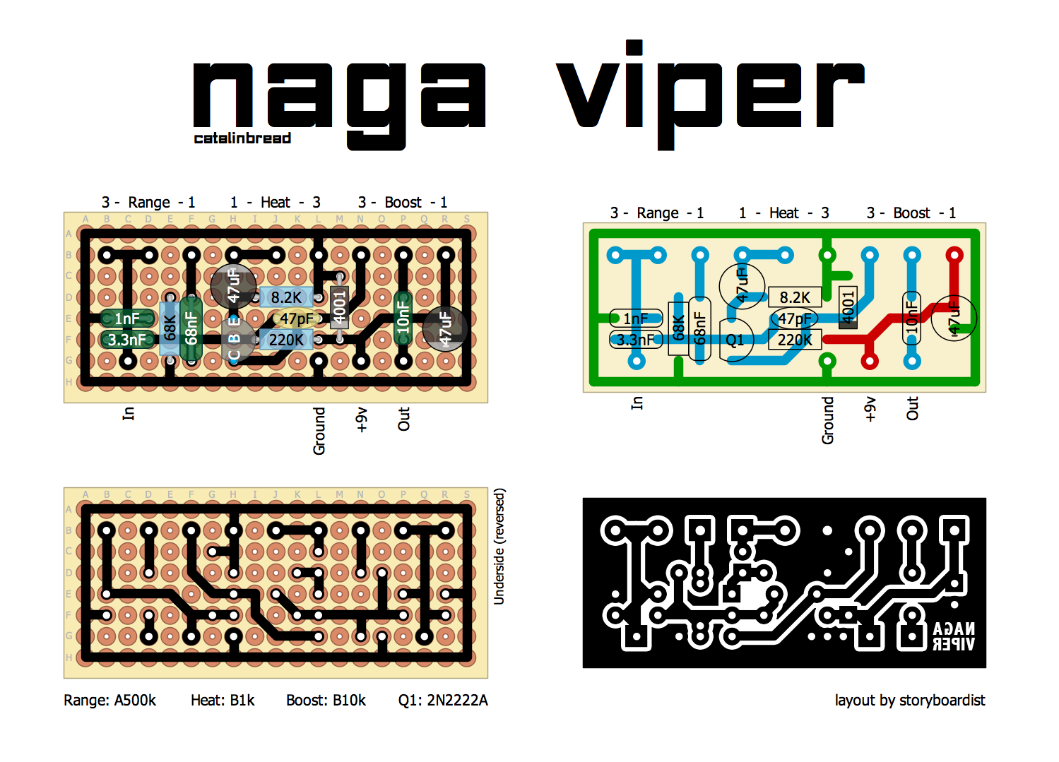
Do you have any idea what could be wrong? Thanks!
I used all the components shown on the board and the PCB was exactly made like this.
Do you have any idea what could be wrong? Thanks!
-
Manfred
- Tube Twister
Information
- Posts: 1945
- Joined: 04 Apr 2009, 23:42
- Has thanked: 1675 times
- Been thanked: 1360 times
Please post pictures from both side of your board and also of the wiring.Aeroblus wrote: ↑17 Apr 2023, 13:10 Hello everyone! I need your help. I am new to DIY pedals. I made the Naga Viper pedal from this diagram and it doesn't sound at all.
I used all the components shown on the board and the PCB was exactly made like this.
Do you have any idea what could be wrong? Thanks!
I got the circuit working, the sound seems to be ok, the potentiometers work fine too. but I have a noise like a pump (I don't know how to describe it) but it is very annoying. This noise happens to me when I'm playing and when I'm not playing. Thanks!Manfred wrote: ↑17 Apr 2023, 14:03Please post pictures from both side of your board and also of the wiring.Aeroblus wrote: ↑17 Apr 2023, 13:10 Hello everyone! I need your help. I am new to DIY pedals. I made the Naga Viper pedal from this diagram and it doesn't sound at all.
I used all the components shown on the board and the PCB was exactly made like this.
Do you have any idea what could be wrong? Thanks!
https://ibb.co/Yj2R42X
https://ibb.co/FgcwsqP
https://ibb.co/TqTnjZV
-
Manfred
- Tube Twister
Information
- Posts: 1945
- Joined: 04 Apr 2009, 23:42
- Has thanked: 1675 times
- Been thanked: 1360 times
How do you power the pedal with DC adapter or with battery?I got the circuit working, the sound seems to be ok, the potentiometers work fine too. but I have a noise like a pump (I don't know how to describe it) but it is very annoying. This noise happens to me when I'm playing and when I'm not playing. Thanks!
With a DC adapterManfred wrote: ↑19 Apr 2023, 23:13How do you power the pedal with DC adapter or with battery?I got the circuit working, the sound seems to be ok, the potentiometers work fine too. but I have a noise like a pump (I don't know how to describe it) but it is very annoying. This noise happens to me when I'm playing and when I'm not playing. Thanks!
-
Manfred
- Tube Twister
Information
- Posts: 1945
- Joined: 04 Apr 2009, 23:42
- Has thanked: 1675 times
- Been thanked: 1360 times
Try if the noise disappears when you use a battery.Aeroblus wrote: ↑20 Apr 2023, 13:45With a DC adapterManfred wrote: ↑19 Apr 2023, 23:13How do you power the pedal with DC adapter or with battery?I got the circuit working, the sound seems to be ok, the potentiometers work fine too. but I have a noise like a pump (I don't know how to describe it) but it is very annoying. This noise happens to me when I'm playing and when I'm not playing. Thanks!
If the noise is then gone, it may be due to the power supply, otherwise perhaps a grounding problem.
Thanks for the advice. When I'm using a battery the noise goes away, but it's the only circuit that has noise with a DC adapter.
Do you have any idea?
I made two more circuits, a Blues Breaker and a RIFT EL34 from the same website and they work perfectly with the DC adapter.
Do you have any idea?
I made two more circuits, a Blues Breaker and a RIFT EL34 from the same website and they work perfectly with the DC adapter.
-
karul
- Cap Cooler
It's hard to tell when you are not providing any info what kind of a "dc adapter" you are using. Is it regulated, what king of regulation? Is it SMPS? Is it simple dc wall adapter, or for pedal use? You could have make a photo of it, provide detailed info and make it easier for the guys to be more helpful.Aeroblus wrote: ↑24 Apr 2023, 12:34 Thanks for the advice. When I'm using a battery the noise goes away, but it's the only circuit that has noise with a DC adapter.
Do you have any idea?
I made two more circuits, a Blues Breaker and a RIFT EL34 from the same website and they work perfectly with the DC adapter.