THE ENGINEER'S THUMB... At last, a better compressor! [documentation]
Hi Merlin built this one from harald's layout, I must say that of all the compressor's I've played so far this one will kill it all, awesome job; but I would really like to know how do you play around with the threshold and ratio knobs? how do they interact, if you can throw some light I will be highly obliged. 
They're not really interactive as such. Not electrically anyway.travorkates005 wrote:Hi Merlin built this one from harald's layout, I must say that of all the compressor's I've played so far this one will kill it all, awesome job; but I would really like to know how do you play around with the threshold and ratio knobs? how do they interact, if you can throw some light I will be highly obliged.
The threshold determines how big the input signal has to be before compression starts happening; its a sort of 'trigger level'. The minimum level is 20mVp-p, same as a Dynacomp. Signals greater than 20mVp-p will be compressed. If you include the threshold pot then you can raise that trigger level, so the signal has to be larger before any compression happens.
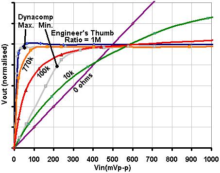
The ratio control determines how much compression happens. When set to zero resistance there is no compression at all, just unity gain (purple line below). At max resistance you get hard limiting- everything above the threshold level comes out at the same volume (blue line). At intermediate ratio settings the compression increases with the signal input (e.g. green line)
I guess they feel interactive because the ratio control changes how much gain for signals below the trheshold. If you have a compression curve like this:

A non-interative ratio control would be able change the slope of the curve after the threshold without changing the slope of the curve before the threshold (I think in the ET it's more like the opposite). And changing the threshold would mean changing the location of the knee withou changing either slope. That would result in lower output levels as you lower the trheshold. They being "interactive" as they are, is good thing IMHO, because it's like if you had "automatic make up gain" as they call it in compressor plug-ins And if making it "non-interactive" can make the circuit more complicated and LESS practical, the "interaction" is a good thing.
I only have not build this yet because I'm waiting for the version with a GR led bargraph I think I'll just attach a 3916 to the (-) pin of U2A.
A non-interative ratio control would be able change the slope of the curve after the threshold without changing the slope of the curve before the threshold (I think in the ET it's more like the opposite). And changing the threshold would mean changing the location of the knee withou changing either slope. That would result in lower output levels as you lower the trheshold. They being "interactive" as they are, is good thing IMHO, because it's like if you had "automatic make up gain" as they call it in compressor plug-ins
I only have not build this yet because I'm waiting for the version with a GR led bargraph
That's true. In the ET, the ratio control automatically adds make-up gain as you increase the ratio. A happy accident of design!Guilherme wrote: They being "interactive" as they are, is good thing IMHO, because it's like if you had "automatic make up gain" as they call it in compressor plug-ins
Threshold control doesn't interact- it does what it says on the tin.
Merlin,
The blue line in your graph shows what happens with a high ratio (limiting), low threshold. So it works like a sustainer, like we are used to with guitar "compressors".
If I wanted to use it with as a limiter, with the high ratio, but with a high threshold, so that I was just taming the peaks, this topology wouldn't be the most recommended, right? Because with the high ratio I would have a high gain before limiting and perhaps the compressor itself would distort before the limiting?
Actually it is still perfectly suitable as a limiter. The maximum input to the whole circuit is about 5Vp-p without the protection LEDs, so as long as your input signals are smaller than that, you can set the controls however you like. Beyond that and there will be distortion.Guilherme wrote: If I wanted to use it with as a limiter, with the high ratio, but with a high threshold, so that I was just taming the peaks, this topology wouldn't be the most recommended, right? Because with the high ratio I would have a high gain before limiting and perhaps the compressor itself would distort before the limiting?
Please forgive if I insist on the matter, I'm not looking for "deffects" on your design or something like that, I just want to understand the circuit and know the best ways to use it.
Looking at the blue curve, if I set the threshold for 100mV for example, to plot the new curve I Imagine I'd have to extrapolate the inital steep section of blue curve and have a knee only when the input axis is near 100mV, followed by the horizontal section from there on. So the horizontal section of the new curve would be at a higher output level. With the threshold at 100mV, that's 5x the 20mV minimum threshold, and the output would be 5x bigger too. Right? From the purple curve I guess the horizontal section of the blue curve is at a 500mV output level. So if I set the input threshold to 100mV, the output would be limited at 5x that, or 2.5V. If the opamp could swing rail-to-rail, the maximum output would be 9Vpp, and so the maximum input threshold for limiting would be 360mV, not taking in consideration transients spikes during the attack. Problably it's more than OK for guitar, and you can still turn down the ratio a little, for a little less sharp limiting but less before-the-threshold-gain.
Looking at the blue curve, if I set the threshold for 100mV for example, to plot the new curve I Imagine I'd have to extrapolate the inital steep section of blue curve and have a knee only when the input axis is near 100mV, followed by the horizontal section from there on. So the horizontal section of the new curve would be at a higher output level. With the threshold at 100mV, that's 5x the 20mV minimum threshold, and the output would be 5x bigger too. Right? From the purple curve I guess the horizontal section of the blue curve is at a 500mV output level. So if I set the input threshold to 100mV, the output would be limited at 5x that, or 2.5V. If the opamp could swing rail-to-rail, the maximum output would be 9Vpp, and so the maximum input threshold for limiting would be 360mV, not taking in consideration transients spikes during the attack. Problably it's more than OK for guitar, and you can still turn down the ratio a little, for a little less sharp limiting but less before-the-threshold-gain.
Yes, that's probably about right. I didn't think to test it that high though.Guilherme wrote: If the opamp could swing rail-to-rail, the maximum output would be 9Vpp, and so the maximum input threshold for limiting would be 360mV, not taking in consideration transients spikes during the attack. Problably it's more than OK for guitar, and you can still turn down the ratio a little, for a little less sharp limiting but less before-the-threshold-gain.
Here are plots I did for response at different threshold settings, showing the full range of input signal levels until gross distortion occurs (more than 6Vp-p under the right conditions!). Vol pot at the maximum setting. Ratio at max setting.
The percentages refer to the amount of threshold pot rotation, assuming a linear pot.

Here is the same graph zoomed in to show only input signals up to 1Vp-p:

Thanks a lot merlinb for the detailed explanation.........

-
ppluis0

- Diode Debunker
Thank you for your answer, Merlin.
Just I see in your original schematic posted at the beginning of this thread that the attack resistor can vary from 100 ohms to 100K, so a 1 Meg potentiometer is a reasonable choice.
Cheers,
Jose
Just I see in your original schematic posted at the beginning of this thread that the attack resistor can vary from 100 ohms to 100K, so a 1 Meg potentiometer is a reasonable choice.
Cheers,
Jose
Hi Folks.
I've built an engineer's thumb using the JMK PCB rev 1.2 and I can't seem to get the circuit to start and compress until the input is greater than approx 600mV p-p. I'm looking for compression by monitoring the input waveform (1kHz) with one channel of a scope and the output with the second channel and I can't see the output compressing until the input is approx 600mV p-p.
Here's a link to the circuit http://jmkpcbs.com/wp-content/uploads/2 ... -Thumb.pdf
The following are DC voltage readings with no signal (9v power):
TL074
pin 1 =4.69v
pin 2 =4.51v
pin 3 = 4.11
pin 4 = 0v
pin 5 = 4.11
pin 6 = ?
pin 7 = 4.56
pin 8 = 3.86
pin 9 = 4.4
pin 10 = 4.02
pin 12,13,14 = 4.5v
CA3080
pin 2 = 4.51v
pin 3 = 4.51v
pin 5 = 0.69
pin 6 = 4.51
I beleive the problem has something to do with the precision rectifier circuit as the waveform on pin 1 of the TL074 looks nothing like half wave rectification, in fact the waveform is still a full sinewave until the above 600mV input is reached and only then does the bottem of the negative half cycle start to show signs of a more negative spike. I've even tried simulating this circuit using 5Spice which seems to give the same results. All the precision rectifier circuits I've seem on the internet have the feedback to the same input as its signal input. The only changes I've made from the orginal circuit are using 1uF electro in place of C5 and C6 and a BC 327 in place of Q1.
I would appreciate if someone with more knowledge of the type of circuit give me some advice, please?
Regards
Geoff
-
modman

- a d m i n
Information
- Posts: 4898
- Joined: 19 Jun 2007, 16:57
- Has thanked: 4411 times
- Been thanked: 2139 times
This circuit was first published here: viewtopic.php?f=13&t=17213
http://jmkpcbs.com/ seem to have a forum connected: http://www.madbeanpedals.com/forum/index.php?board=26.0
http://www.thegearpage.net/board/showth ... ?t=1239689
Jacob is a great guy!
http://jmkpcbs.com/ seem to have a forum connected: http://www.madbeanpedals.com/forum/index.php?board=26.0
http://www.thegearpage.net/board/showth ... ?t=1239689
Jacob is a great guy!
Please, support freestompboxes.org on Patreon for just 1 pcb per year! Or donate directly through PayPal
-
Mbas974

- Resistor Ronker
Ok resurrection.....
Sabro Layout is showing Treshold Pot leg2 goes into IC1(+)IN and leg3 goes into IC2(+)IN
while
ValveWizard schem leg2 and leg3 are shorted
is it a MOD ? or a mistake on Sabro ?
TX
Sabro Layout is showing Treshold Pot leg2 goes into IC1(+)IN and leg3 goes into IC2(+)IN
while
ValveWizard schem leg2 and leg3 are shorted
is it a MOD ? or a mistake on Sabro ?
TX
-
snk

- Resistor Ronker
Hello
I am considering building this compressor.
Is there any way to ad a led to show when the compression is actually compressiing ? (or, even better, a led becoming brighter the more it is compressing) ?
Thank you
I am considering building this compressor.
Is there any way to ad a led to show when the compression is actually compressiing ? (or, even better, a led becoming brighter the more it is compressing) ?
Thank you
-
roseblood11
- Tube Twister