I use Eagle and then do some work in Photoshop. Thanks for the complimentroseblood11 wrote:Interesting!
Madbean, which program do you use for your layouts? They really look good!
Blackstone Appliances - MOSFET OD (2SV3.12) [ goop-alarm ] [traced]
-
madbean

Information

-
pandadandan
- Breadboard Brother
Have had a chance to play with the build for a while.
Initially, I wasn't so bowled over; everything seemed a bit woolly and undefined. A few trimpot tweaks later and...
HOLY CRAP IT'S MY FAVOURITE DRIVE PEDAL EVER!
Just putting it on with the drive controls at 9 o'clock gave my amp this really rich, dense sound. Similar to when you crank the preamp gain on a clean amp. Extra warmth and completely natural-sounding. Diming the "standard" gain and turning the secondary gain up high produced some awesome Marshall-esque chug tones which again sounded especially amp-like.
I'm going to be using this a LOT in the coming months.
Big thanks to Madbean for the PCB. Worked like a treat.
HIsomeone could tell me where to connect the booster 3pdt so I have two channels? Madbar says in the circuit can be done, but do not understand how I would have to do .. I hope someone help me??????
"madbean says. you can use either an internal trimmer for boost or external pot (recomended) you could also wire the boost control to another 3pdt to give you second channel"
sorry but I do not understand how this is done, someone could make a drawing??
thanks
"madbean says. you can use either an internal trimmer for boost or external pot (recomended) you could also wire the boost control to another 3pdt to give you second channel"
sorry but I do not understand how this is done, someone could make a drawing??
thanks
-
roseblood11
- Tube Twister
Hi,
there are complete wiring diagrams (which give the answer to both of your questions) in madbeans project file ("Mysterioso Sr."). If you don´t find it here, it´s on his website.
regards, Immo
there are complete wiring diagrams (which give the answer to both of your questions) in madbeans project file ("Mysterioso Sr."). If you don´t find it here, it´s on his website.
regards, Immo
roseblood11 wrote:Hi,
there are complete wiring diagrams (which give the answer to both of your questions) in madbeans project file ("Mysterioso Sr."). If you don´t find it here, it´s on his website.
regards, Immo
hi thanks for replying, the words that I place the file pull Mysterioso jr. but the point is there in that file does not say or indicate how to wire the booster SW2, and leds
means??
expect an answer thanks
-
madbean
Information
You can wire the pot to a 3pdt. One side of the 3pdt is bypass, so the signal passes straight though without going to the pot. When the switch is engaged, it goes to the pot and acts as a boost/more gain.Colca wrote:HIsomeone could tell me where to connect the booster 3pdt so I have two channels? Madbar says in the circuit can be done, but do not understand how I would have to do .. I hope someone help me??????
"madbean says. you can use either an internal trimmer for boost or external pot (recomended) you could also wire the boost control to another 3pdt to give you second channel"
sorry but I do not understand how this is done, someone could make a drawing??
thanks
I can draw up a wiring diagram if you need it.
madbean wrote:You can wire the pot to a 3pdt. One side of the 3pdt is bypass, so the signal passes straight though without going to the pot. When the switch is engaged, it goes to the pot and acts as a boost/more gain.Colca wrote:HIsomeone could tell me where to connect the booster 3pdt so I have two channels? Madbar says in the circuit can be done, but do not understand how I would have to do .. I hope someone help me??????
"madbean says. you can use either an internal trimmer for boost or external pot (recomended) you could also wire the boost control to another 3pdt to give you second channel"
sorry but I do not understand how this is done, someone could make a drawing??
thanks
I can draw up a wiring diagram if you need it.
please brian, I need the diagram, it would be nice if you did ..
I did the pedal and it is fantastic but I do not finish with this
thanks genius
I have a little noob question. Aren't each of those mosfet inverter pairs on the cd4049ub identical? Then why are the pairs out of order in the schematic, causing you to cross over the signal multiple times. On the pins of the opamp why does it go through 7-6, 3-4, then 5-2? Why doesn't it just go 7-6, 5-4, 3-2? Am I missing something? I checked the datasheet and it says that they are identical, so I should be able to use them in any order I please, right?
-
bucksears
- Solder Soldier
So by simply bypassing the 'Boost' pot, that completely takes the boost section out? If so, that should be an easy wiring job and could include an LED to indicate when the boost is on or off.
And the 'Mid' switch is only applicable in 'Boost' mode?
Sorry, I'm a little late to the party on this one, but looks like Madbean did an awesome job.
Thanks,
Buck
And the 'Mid' switch is only applicable in 'Boost' mode?
Sorry, I'm a little late to the party on this one, but looks like Madbean did an awesome job.
Thanks,
Buck
Information
- Posts: 3
- Joined: 08 Aug 2010, 05:44
- my favorite amplifier: Fender Deluxe Reverb
- Completed builds: GGG ITS8; an induction coil; and the "Mojo Bag", which is a pedalboard unit I created out of an old soft leather briefcase.
Next up is madbean's Mysterioso Jr and Neutrino. - Location: Long Beach, California, USA
Wow! I joined up after reading thru the public version of this thread, and wanted to say thanks to everyone involved; I used a Blackstone years ago for a brief tour in Italy, and it's haunted me ever since. I'll be building Madbean's Jr. circuit into an EB volume pedal, and using the footpedal to sweep thru one of the controls. No on/off switch, as mine will be always on; I love being able to go from cleanish to dirty tube tones with a flick of the volume knob on my guitar. 
One thing I really, really dug about the Blackstone was the screwtip pot controls, something I'd like to add to a few of the pedals in my rig; it looks like the pots themselves got sussed pretty early on, but I could not fine the screwtip knobs anywhere on the linked resources, did I miss something?
Good times, and thanks also for lettin a rookie join yall; I'm sure my build effort will be amusing.
-
madbean
Information
Those screwtips were just floating on top of some regular 9mm alphas. I don't know if that is something alpha has available, or custom made, or hardware store parts.
Information
- Posts: 3
- Joined: 08 Aug 2010, 05:44
- my favorite amplifier: Fender Deluxe Reverb
- Completed builds: GGG ITS8; an induction coil; and the "Mojo Bag", which is a pedalboard unit I created out of an old soft leather briefcase.
Next up is madbean's Mysterioso Jr and Neutrino. - Location: Long Beach, California, USA
madbean wrote:Those screwtips were just floating on top of some regular 9mm alphas. I don't know if that is something alpha has available, or custom made, or hardware store parts.
I'll roll with stainless steel machine screws, and just tap some split shaft pots. I sent you an email on yer website earlier, going to be getting your PCB for this thing, and another one as well.
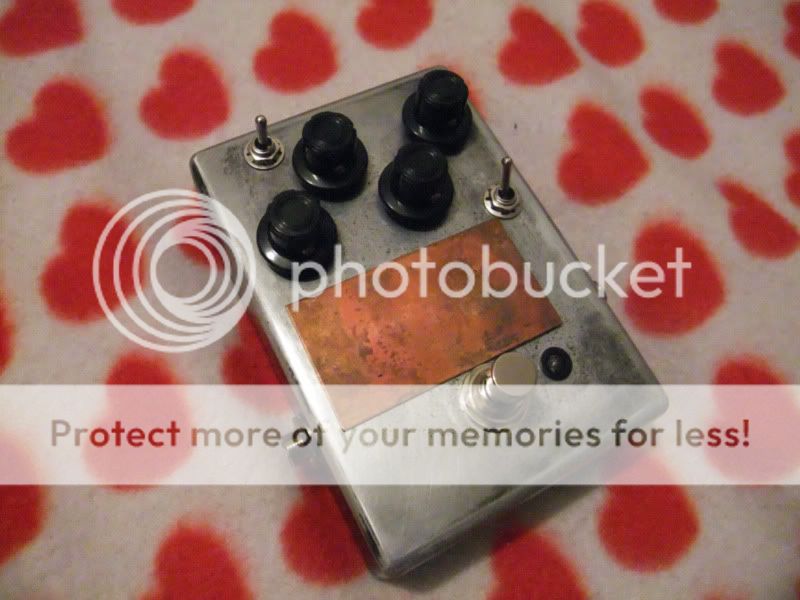
Here's the enclosure I'm going to use; not sure which control I'll run with the pedal, mebbe drive?

You guys think the open enclosure will offer enough shielding? Seems to work okay on the EB wah pedal I have.
-
Greg

- Old Solderhand
Are you saying the signal goes in and out of phase ?condorface wrote:I have a little noob question. Aren't each of those mosfet inverter pairs on the cd4049ub identical? Then why are the pairs out of order in the schematic, causing you to cross over the signal multiple times. On the pins of the opamp why does it go through 7-6, 3-4, then 5-2? Why doesn't it just go 7-6, 5-4, 3-2? Am I missing something? I checked the datasheet and it says that they are identical, so I should be able to use them in any order I please, right?
If so, phase changes within the IC are irrelevant.. it's only the resultant phase at the output that matters.
culturejam wrote: We are equal opportunity exposure artists.
-
mictester

- Old Solderhand
Information
No! The "B" version is "Buffered", and the "UB" version is "Unbuffered". The unbuffered device can be used linearly (that is: in an audio amplifier circuit), the buffered version is confined to digital input and output levels (+ve or ground).jkoncima wrote:Can I use a HEF4049B in the place of the CD4049UEB?
"Why is it humming?" "Because it doesn't know the words!"
-
JiM

- Diode Debunker
Information
- Posts: 967
- Joined: 11 Mar 2008, 22:56
- Completed builds: Completed builds :
Proco Rat
MXR MicroAmp in a volume pedal
TubeDriver (w/ NoS russian tube and big muff tone contol) + Phase 45 (w/ univibe cap ratio)
Dallas Rangemaster (w/ noisy OC75, negative ground)
SubCaster tube booster (w/ NoS russian tube, PtP)
Hot Harmonics
Music From Outer Space SubCommander in progress
Crackle Not OK
Simple bass blender in a 1590A
Bazz Fuss with a photo-darlington - Location: France
- Has thanked: 70 times
- Been thanked: 66 times
- Contact:
It's not about phase, but about layout.Greg_G wrote:Are you saying the signal goes in and out of phase ?condorface wrote:I have a little noob question. Aren't each of those mosfet inverter pairs on the cd4049ub identical? Then why are the pairs out of order in the schematic, causing you to cross over the signal multiple times. On the pins of the opamp why does it go through 7-6, 3-4, then 5-2? Why doesn't it just go 7-6, 5-4, 3-2? Am I missing something? I checked the datasheet and it says that they are identical, so I should be able to use them in any order I please, right?
If so, phase changes within the IC are irrelevant.. it's only the resultant phase at the output that matters.
condorface, you can swap inverters (or opamps, or whatever) within a chip on the schematic to ease board layout, they are indeed identical and on the same silicon die. For example, Eagle CAD has a function for that very purpose, it's called "gate swap".
Beware of noise and crosstalk though, when you're doing a compact layout for a high-gain circuit.
I only give negative feedback.
Information
- Posts: 3
- Joined: 08 Aug 2010, 05:44
- my favorite amplifier: Fender Deluxe Reverb
- Completed builds: GGG ITS8; an induction coil; and the "Mojo Bag", which is a pedalboard unit I created out of an old soft leather briefcase.
Next up is madbean's Mysterioso Jr and Neutrino. - Location: Long Beach, California, USA
Ok, PCB ordered, you guys like build threads around here, and if so, should I put it on this thread, or start another? I'll likely have plenty of questions for the experts on components (brands being a big one, and overspec'd wattage ratings another). Yall might enjoy my hillbilly engineering methods, if nothing else; just sourced a type of T-nut at Ace to dispense with actual knobs. 