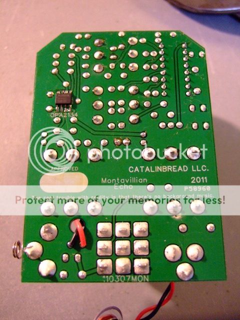
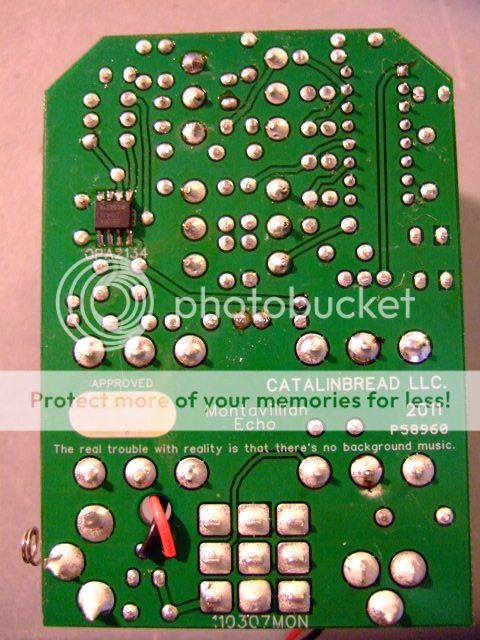
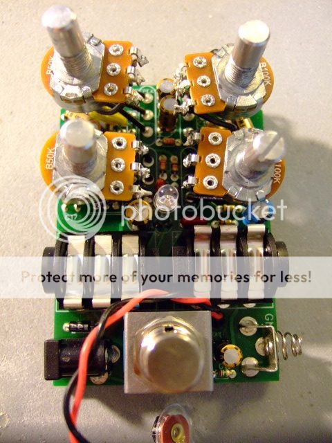
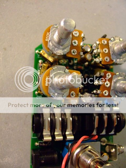
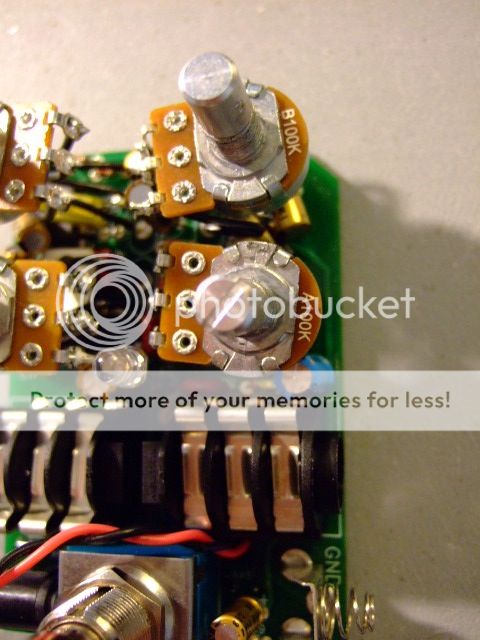
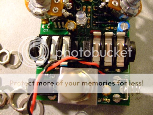
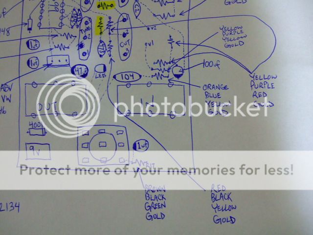
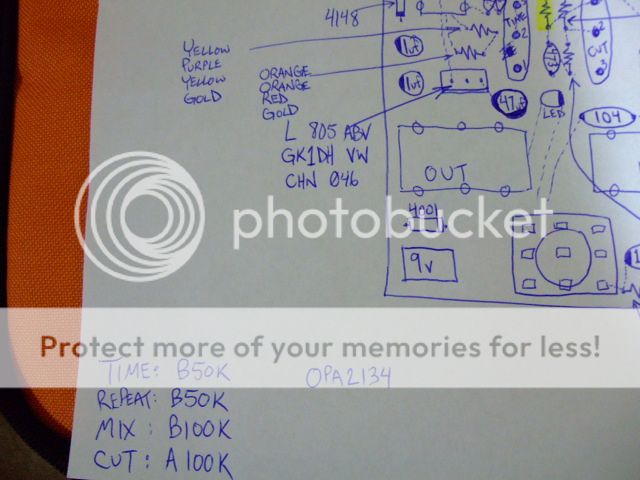
Another PT2399 delay - this is probably my favourite so far - mostly due to the cut knob, it really filters the repeats nicely, and is very interective with the feedback control. you can get some really nice washed out, infinite repeat type of textures.
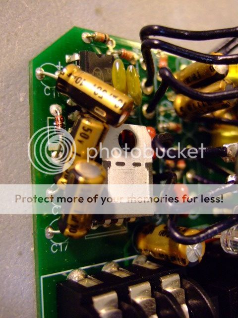
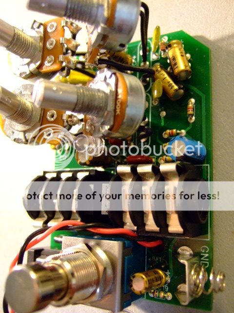
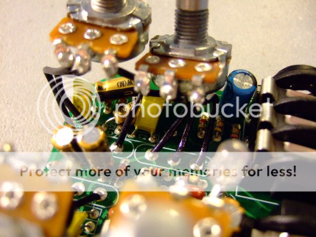
this is going back on my board pretty soon, so let me know if you want values, more pics etc etc
J
"Rock music is mostly about moving big black boxes from one side of town to the other in the back of your car."
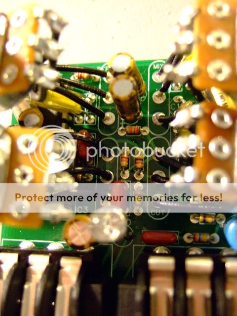
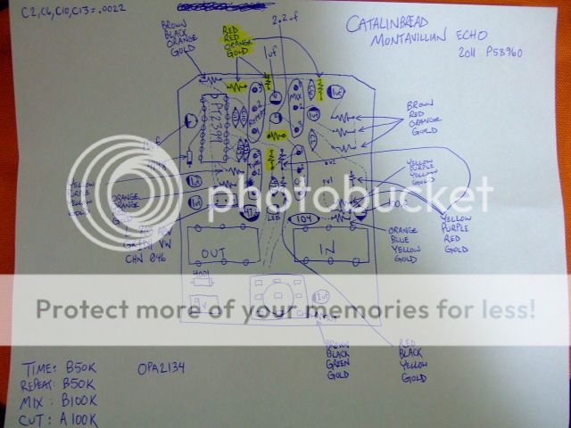
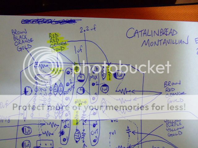
Probably the most important thing is to know how the Cut control is set up. Where does it sit in the circuit, and how does it do the cut? That's what we really want to know/see.
anyway, given the description of its function, the cut circuit is likely found in the feedback path. who knows though. nic and howard are making some crazy stuff these days.
I'm a "professional."
Buy my products and make me rich.
Jack Deville wrote:anyway, given the description of its function, the cut circuit is likely found in the feedback path. who knows though. nic and howard are making some crazy stuff these days.
I did a high cut pot in the feedback path once. It was really nice. As the highs were rolled off, the oscillation point got much easier to achieve. Pretty interesting interaction between the feedback control and the high cut control.
sallen-key low pass filters are popular with this chip as they are suggested in the datasheet.
manipulating fixed resistance values can do all kinds of strange things to the response of the filter.
set one up and run some simulations!
could be a nice way to keep the parts count low and utilize what's already there, if that's already there, that is...
I'm a "professional."
Buy my products and make me rich.
I think this is the first pt2399 design I'm interested in. I've tried a couple of Rebote delays and some other designs, but none could match the spacious quality of the Montavillian. Looking forward to this one, even though I might buy one myself.
DWBH wrote:I think this is the first pt2399 design I'm interested in. I've tried a couple of Rebote delays and some other designs, but none could match the spacious quality of the Montavillian.
I think a lot of problems with noise and lo fidelity are due to variations from chip to chip. Wampler has said that he sorts through 2399s for his Faux Tape Echo pedal, and that his rejection rate is quite high.
Of course, smart filtering is also critical, but some 2399s are just really bad sounding, and some are much better.
That's true, some 2399's are too noisy, some other have a hard time to "start" on short delay settings etc... I'll like to see the filtering section, I never could get rid of the hiss of the 2399 without making the repeats too muddy.
Sweetalk wrote:Pin 4 on the pt it's digital ground, the delay pot also hass to be reffered to digital ground. The diode is to separate digital and analog grounds.
There has been a lot of gnashing of teeth over exactly what difference there is between the two grounds. Pretty much all the testing that has been done has yielded no difference between them, no matter how things are set up.
So could you go into detail about the diode/digital ground thing a bit more? Obviously, the diode is keeping pin 4 at about 0.7v above ground. But what does that accomplish?
More importantly, what does it sound like?
Thanks
Generally speaking, people try to keep digital and analog grounds separate for noise purposes...which I assume could have an impact on reducing things like feedback, oscillation, and all that 0's and 1's stuff from getting nasty and out of hand-whatever that looks like.
Liquids wrote:Generally speaking, people try to keep digital and analog grounds separate for noise purposes...which I assume could have an impact on reducing things like feedback, oscillation, and all that 0's and 1's stuff from getting nasty and out of hand-whatever that looks like.
That makes sense.
But as I understand it, pins 3 and 4 are internally connected to each other (or at least only separated by a few ohms). So I think if you use a diode on pin 4, it's basically doing the same thing to pin 3.
There is no need for that diode to ground nor for connecting pin 4 to ground because it is already connected to a pin 3 (ground) internally via ~10 ohm resistor.
Digital and analog grounds dont need to be seperated, but a proper component placement with some carefull routing and foremost proper partitioning is the key to success in laying out mixed signal board.