Good day,
I'm trying to fix my phase 95 mini. smd
the 90mode is inaudible, the 45 is working fine.
I thought the switch was the problem, but seem like the mxr switch is different from the center common switch I used.
I know is PITA to work on smd , but If someone can help which component to check or replace, i can work things out.
Sorry I dont know which schematic they used for this too
here's the board
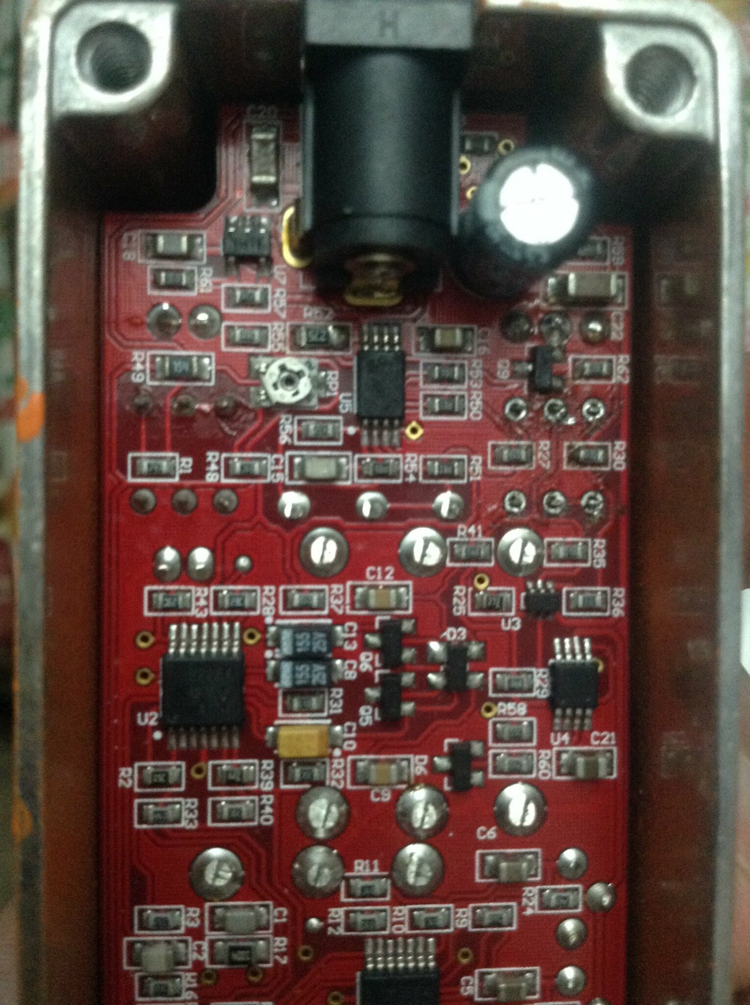
the 45/90 switch is on the right on this pic. I just desoldered it from the pic, it's well soldered now
here's a video
Thanks!
mxr phase 95 mini : 90mode inaudible
Information
- Posts: 1
- Joined: 02 Apr 2023, 06:55
Hi, now is 2023. Not sure if you have ever found solution or not. I've fixed it luckily hope it can help somebody.
I just bought an used MXR Phaser 95 from local guitarist. The problem is same as yours. Barely no output when switched to 90 mode. I tried to debug it but the SMD layout has too much components I don't have much time to track back the actual schematic. Finally I was very lucky to have fixed it.
The PCB layout design is pretty weird. As the PCB picture you posted. The right side 6 pin DPDT switch (which is for selecting 90/45), 2 pins between R30 & R35 (lower right 2 of 6 pins) is tied together. Which means this node will be always conducted with another pin below R27 no matter this DPDT is on or off. I am not sure whether the lower side SPDT of 6 pin DPDT was soldered or not. Whatever my Phaser 95 is worked normally after I cut off these 3 pins.
I still very curious about the original design so I'm trying to googling something and I only find this post. Whether this DPDT switch was only soldered one side or it is a special switch has customized switching rule? I just wonder it.