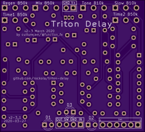
Did this one a while back but thought I'd share here. I took the basic bones of the Deep Blue Delay (changed some filtering values), added a variable LPF on the delay output (via trimmer/cap), added a second Delay Time control with a slow transition when switching between Time 1 and Time 2. It works
similar to some versions of the Toneczar EchoCzar how it does the "glide" between Time pots. Probably more of a curiosity than something you'd actually use all the time, but it's fun to play around with.
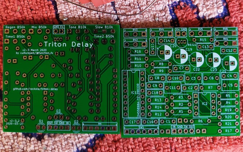
I just updated a few values on the drawing today based on the last one I built (which I think is the best sounding one I've done). I've also attached photos of a build I completed (and one I'm about to box up).
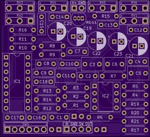
If you want to monkey with making the transition time (and resulting pitch-bend glissando effect) longer, make C20 larger.
Any questions, feel free to ask!