Here's a fun tremolo! It's a pedal I had for a while, I didn't took the time to trace it until now.
The board is kind of a mess but I proceeded carefully.
Of course the chip names are sanded, but the 4017 is quite obvious. For the double op-amp, anything works pretty much, I tested the TL072, RC4558 and LM358.
The stop switch is for stopping the clock, a bypass is still needed. This switch is part of the 3PDT bypass footswitch. When the pedal is bypassed, the stop switch is closed.
The logic and audio components were carefully separated with ground planes on the board. This tells me the circuit could be noisy, so be careful.
EDIT: Changed to CD4017BE
EDIT: Changed R4 to 5k1
Zvex - Seek Trem [traced]
Hey, thanks for the heads up I'll change it for CD4017BE which apparently goes up to 18V.
Science is art. Art is science.
https://electric-canary.com
https://electric-canary.com
-
xaxxop

- Breadboard Brother
Hello!
Thank you so much for tracing this one.
How do you separate the ground planes for logic and audio?
I can’t see Q2 on the board
Thank you again
Leo
Thank you so much for tracing this one.
How do you separate the ground planes for logic and audio?
I can’t see Q2 on the board

Thank you again

Leo
Leandro
-
plush

- Cap Cooler
It seems to me that you are confusing 2 different things here: isolating logic ground from signal ground and isolating networks with a proper ground plane (also called "guard ring").
There's no need to isolate logic ground from signal ground here.
As for the guard ring, it is done to remove possible capacitive leakage between signal lines (analogs and/or digitals) by drawing a ground plane between them (google "pcb ground plane" for more details).
In most cases, when you are working on analog stuff, adjusting your DRC so that the ground can be poured between the traces automatically, is the easiest solution. But in some particular cases,when you are working with digital stuff at higher frequencies (hundreds of khz and over), such thing can introduce additional capacitance to the digital traces and lead to circuit malfunction.
Sometimes noise can also be coupled back into the circuit electro-magnetically (via radiated emision), in such cases you may want to reroute your wiring (shield at least the input wire), or move the oscillator and it's routing to the most distant part of the pcb (potentially to the bottom side of it) and pour ground plane over top of it.
-
xaxxop
- Breadboard Brother
Wow thank you so much plush for the explanation, I got a lot to learn yet! I really fancy making a PCB for the seek trem and the seek wah.
Thanks leo
Thanks leo
Leandro
Hey!
Not gonna add anything to what plush said, it's very well explained.
Q2 is hidden under the op-amp. Actually it's inside the socket, first time I see that.
The package is more compact than a standard to-92. I didn't manage to find it's name.
Science is art. Art is science.
https://electric-canary.com
https://electric-canary.com
-
Bernardduur

- Transistor Tuner
One adddition; in the unit that is now on my bench, R4 = 5k1
'No more....... loud music.......'
Follow my love for pedals and amps on https://bernardduur.blogspot.com and https://www.instagram.com/bernardduur1
Follow my love for pedals and amps on https://bernardduur.blogspot.com and https://www.instagram.com/bernardduur1
I checked mine again and yes it is. I edited the schem, thanks a lot!
Science is art. Art is science.
https://electric-canary.com
https://electric-canary.com
Those 2M7 resistors. Could someone explain their function to me? I am not that adept... Could these be subbed with say 2M2? Or I guess I could use a 2M2 and a 470K in series to get closer to the 2M7. I just don't have anything of that value. But I do have 2M2 and 470k...

Thanks for the info. I'll go that route.
Next question... I don't have any 1N757A here, nor any other zener diodes of that voltage. Is there some work-around for this? What is it's function in the circuit?
I was thinking of just using the audio section from the Tremulous Lune instead of this Zvex section, but would like to try it how it is designed.
Actually... Looking at it further, this is just a protection diode, right? This could likely be omitted? Thoughts?
-
Nocentelli

- Tube Twister
Information
- Posts: 2222
- Joined: 09 Apr 2009, 07:06
- Location: Leeds, UK
- Has thanked: 1155 times
- Been thanked: 954 times
It will function without. I think i heard that zvex added it after some sho's got returned with blown mosfets way back
modman wrote: ↑ Let's hope it's not a hit, because soldering up the same pedal everyday, is a sad life. It's that same ole devilish double bind again...
Makes sense. A bit of protection for the builder.
Another question about this... I have it on my breadboard with the tremulous Lune audio side instead right now, and the ticking from the sequencer is crazy loud. Is this just going to be a given on a breadboard with this circuit, seeing as I have wires going all over?
Another question about this... I have it on my breadboard with the tremulous Lune audio side instead right now, and the ticking from the sequencer is crazy loud. Is this just going to be a given on a breadboard with this circuit, seeing as I have wires going all over?
-
Nocentelli
- Tube Twister
Information
- Posts: 2222
- Joined: 09 Apr 2009, 07:06
- Location: Leeds, UK
- Has thanked: 1155 times
- Been thanked: 954 times
every 4017-based circuit I have tried has had serious tick on the breadboard, I haven't ever progressed to boxing one up but I suspect this would improve matters somewhat.
modman wrote: ↑ Let's hope it's not a hit, because soldering up the same pedal everyday, is a sad life. It's that same ole devilish double bind again...

Hi everyone! For a while, I've wanted to make this one, a lot of tremolos with tons of versatility. I call mine "Tremolo Factory" for the plenty of complex tremolos it produces. Below, I attached some pictures of the finished build and the schematic.
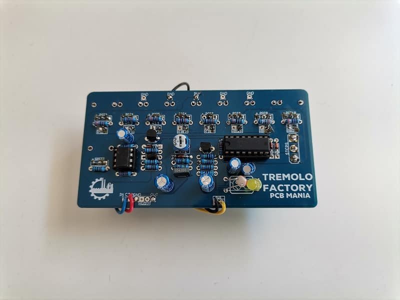

I replaced the vactrol with a photoresistor and a yellow 5mm LED. This is my first take on this circuit, and in this version, the potentiometers work in the anti-clockwise direction. To fix that, I was thinking of making a new version with the potentiometers on the opposite side, along with the components.
This board fits in a 1590bb enclosure.
I recommend this build to anyone looking for a workshop of unlimited tremolos.
I have made some PCBs for anyone who'd like to give it a try!
I'm here to help you building great pedals.
-
Check out our boutique effects PCBs at:
https://pcbguitarmania.com/
-
Check out our boutique effects PCBs at:
https://pcbguitarmania.com/
Information
- Posts: 1
- Joined: 20 Oct 2021, 04:04
I would be very grateful if someone could help a noob out...
I have two questions about this build:
1. What is the value of the capacitor for c26 located just to the left of the 100uf electrolytic cap?it appears to also be 100uf electrolytic, but it wasn’t on the schematic that I could tell.
2. With these small potentiometers (plastic shaft ones) are the two extra legs just for support? Do I need to solder them?
Thanks.
-
cspar
- Breadboard Brother
Hard to tell but it seems like the extra capacitor might be connected to the +9 side of the resistor that limits the indicator led which would mean it's for power filtering.
The schematic doesn't have a filter cap on the +9 so it makes sense.
I'm curious about grounding 9mm potentiometer legs also. I don't use the ones with the legs very much.
The schematic doesn't have a filter cap on the +9 so it makes sense.
I'm curious about grounding 9mm potentiometer legs also. I don't use the ones with the legs very much.
"There is discussion, brainstorming, disagreement, testing, verified layout and schematic. We are the fucking stompbox university -- only for those who still read though..." - Modman
-
Jarno

- Resistor Ronker
Information
- Posts: 363
- Joined: 12 Nov 2008, 10:18
- my favorite amplifier: Something nice
- Completed builds: Alembic-like state-variable and sallen-key filter preamps
Lovepedal Eternity
Phase 100
Brown source
Fuzz Face
Flipster
Alembic F2B (tube preamp)
Opamp and FET buffers
Loads of speakercabinets and ampracks
Busy building a modular synth (ssm2044 vcfs, preamps, ADSR's, VCO's, VCA's)
Tables
Bookshelves
Basses
So many things! :D - Location: Rosmalen, NL
- Has thanked: 27 times
- Been thanked: 81 times
I use a lot of the PCB mount pots, since I also dabble in DIY modular synth modules, and they are often used there. There is no electrical need to solder the support legs, but it does make the mount a lot sturdier. The pot shafts are a bit wobbly though. There are also 9mm vertical PC mount pots with aluminium shafts, and those have a bearing around the shaft which makes them a lot sturdier (and a lot more expensive, especially in conductive plastic, smooooothhh though  ). Those 9mm Alpha pots do use a slightly different footprint, IIRC, maybe just the support legs.
WRT, this circuit, I built a seek wah ages ago, and yeah, take care with the layout of the board and cable routing, because else you'll hear clock noise. I used ribbon cable for the wiring to the set of potmeters, and had to break the ribbon apart, and still you'd hear ticking.
Fun circuit though, both in "wah" and probably also as "trem".
"It crackles....., but that's ok"