Hi all,
How might it be possible to bypass the S/M/L switch on the DD-2 so that the Delay Time controls the entire sweep from short to long?
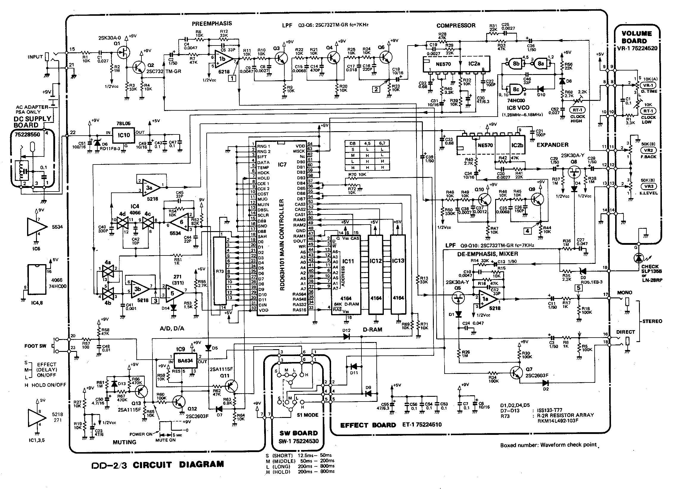
DD-2 schematic for reference:
http://www.8bitsindgenug.net/boss_dd2.png
I'm looking to integrate the DD-2 into a multi-FX board and think this would be a nice feature.
Thanks in advance
Phil
Bypassing Rotary Switch on Boss DD-2
-
stolen

- Breadboard Brother
Hi!
Unfortunately, this is a little bit more involved than just rewiring the circuit a little. The switch exists for a good reason; let's look into why it's there in the first place.
This pedal works quite differently than modern digital delays, and is actually closer to a classic BBD delay, with a 570 compander and all. The microcontroller delays the signal by a fixed amount of samples, and by changing the sample rate via the clock VCO in the upper right hand corner continuous control over delay time is achieved. The switch chooses by how many samples the signal is delayed so that the sample rate stays within reasonable bounds for all delay times. A modern delay would do this purely in software; while adjusting the delay time in steps of 1 sample is trivial, continuous control would require interpolation. A modern microcontroller can easily do this without breaking a sweat, but from an economic early 80s model that is quite a lot to ask.
In order to get rid of the switch, we'd therefore have to control the oscillator that changes the sample rate and the GPIOs that determine the sample delay. This is not too hard; the angular travel of the potentiometer must be mapped to a control voltage in a sawtooth-like manner (with 3 blades), and the GPIOs must be switched when this sawtooth "jumps". This can be implemented in a purely analog manner with a few comparators and summing amplifiers, but it's quite the parts count; a cheap microcontroller with a DAC would probably be the easier way to go about this (we wouldn't recommend a PWM DAC here since filtering would have to be quite strong to reduce clock ripple to an acceptable amount).
However, this approach isn't perfect: Stitching the sections of the switch together would probably result in delay time jumps; even if you calibrate your heart out, there is some temperature drift with the given circuit. There's two ways to handle this; firstly, you skip the exisiting VCO and have a microcontroller generate the clock directly. It's in the low MHz range, so you'd expect a rather coarse clock resolution from a typical ~100MHz controller if you want to keep the ripple low. It would probably yield better results to use feedback instead and monitor the VCO frequency from the microcontroller and make small corrections to the control voltage in software; you could even divide it down with a binary counter or shift register etc. in order to make frequency analysis easier. Both of these approaches would allow for precise tap tempo to be retrofitted.
Long story short: It's quite some effort, and for good results you must be willing to sit down for a while and write some firmware. Hope we didn't dishearten you too much, it's not inconceivable that there is a simpler option that we just overlooked.
All the best!
Firstly, thank you so much for your most detailed reply. There is certainly a lot of info there and with that in mind, I think bypassing the switch entirely is not the best option.stolen wrote: ↑15 Mar 2021, 08:50 Hi!
Unfortunately, this is a little bit more involved than just rewiring the circuit a little. The switch exists for a good reason; let's look into why it's there in the first place.
This pedal works quite differently than modern digital delays, and is actually closer to a classic BBD delay, with a 570 compander and all. The microcontroller delays the signal by a fixed amount of samples, and by changing the sample rate via the clock VCO in the upper right hand corner continuous control over delay time is achieved. The switch chooses by how many samples the signal is delayed so that the sample rate stays within reasonable bounds for all delay times. A modern delay would do this purely in software; while adjusting the delay time in steps of 1 sample is trivial, continuous control would require interpolation. A modern microcontroller can easily do this without breaking a sweat, but from an economic early 80s model that is quite a lot to ask.
In order to get rid of the switch, we'd therefore have to control the oscillator that changes the sample rate and the GPIOs that determine the sample delay. This is not too hard; the angular travel of the potentiometer must be mapped to a control voltage in a sawtooth-like manner (with 3 blades), and the GPIOs must be switched when this sawtooth "jumps". This can be implemented in a purely analog manner with a few comparators and summing amplifiers, but it's quite the parts count; a cheap microcontroller with a DAC would probably be the easier way to go about this (we wouldn't recommend a PWM DAC here since filtering would have to be quite strong to reduce clock ripple to an acceptable amount).
However, this approach isn't perfect: Stitching the sections of the switch together would probably result in delay time jumps; even if you calibrate your heart out, there is some temperature drift with the given circuit. There's two ways to handle this; firstly, you skip the exisiting VCO and have a microcontroller generate the clock directly. It's in the low MHz range, so you'd expect a rather coarse clock resolution from a typical ~100MHz controller if you want to keep the ripple low. It would probably yield better results to use feedback instead and monitor the VCO frequency from the microcontroller and make small corrections to the control voltage in software; you could even divide it down with a binary counter or shift register etc. in order to make frequency analysis easier. Both of these approaches would allow for precise tap tempo to be retrofitted.
Long story short: It's quite some effort, and for good results you must be willing to sit down for a while and write some firmware. Hope we didn't dishearten you too much, it's not inconceivable that there is a simpler option that we just overlooked.
All the best!
I only use the Medium and Long settings, I find the Short a bit pointless and I never use the Hold (wouldn't be able to with the DD-2 in an integrated FX system.
With that in mind, would I be correct in thinking that I could wire a DPDT switch to toggle between Medium and Long, on the basis it's a 2P4T switch to start, and "post integration", I only want to use 2 of the 4 functions.
Thanks again in advance
Phil R
-
stolen
- Breadboard Brother
Absolutely, that would be quite chill. You can go even lower! If you look at the switch board in the linked schematic that the upper half doesn't change state in any mode but hold, so if you just permanently connect those wires you'll be fine with an SPDT. But wait, there's more! If you check out the diode logic (specifically D11), you will notice that DB4/DB5 are pulled up in both medium and long modes, and only DB6/DB7 needs to be pulled up! In other words, you can just wire the "M" port on the lower half of the switch to +9V and use an SPST to (dis)connect the "L" port to/from +9V.
Cheers!
Your help has been absolutely invaluable - thank you so muchstolen wrote: ↑15 Mar 2021, 16:56Absolutely, that would be quite chill. You can go even lower! If you look at the switch board in the linked schematic that the upper half doesn't change state in any mode but hold, so if you just permanently connect those wires you'll be fine with an SPDT. But wait, there's more! If you check out the diode logic (specifically D11), you will notice that DB4/DB5 are pulled up in both medium and long modes, and only DB6/DB7 needs to be pulled up! In other words, you can just wire the "M" port on the lower half of the switch to +9V and use an SPST to (dis)connect the "L" port to/from +9V.
Cheers!
