Troubleshooting help - BK/Baja Tube Drive content

Forum dedicated to helping people debug and troubleshoot non-functional pedals or builds. Please use an clear and informative title, indicating circuit and basic problem. Don't forget to mark the issue as fixed if this is the case.
Post Reply
User avatar
Dr Tony Balls
Diode Debunker
Information
Posts: 843
Joined: 07 May 2009, 14:29
my favorite amplifier: Sunn Model T
Location: Brooklyn, NY
Has thanked: 4 times
Been thanked: 172 times

Post by Dr Tony Balls »

Hi all. I'm trying my hand at a BK/Baja Tube Drive kinda thing and running into issues. I'm wondering if there's something i'm not getting. The original units ran off 120VAC, with a transformer to step down to 12VAC. 12VAC went to the tube filaments, and some rectification happened to provide +12VDC and -12VDC rails. Bajaman's unit did the same thing but ran off a 12VAC supply, thus eliminating the internal transformer. Schematic like so:

Image


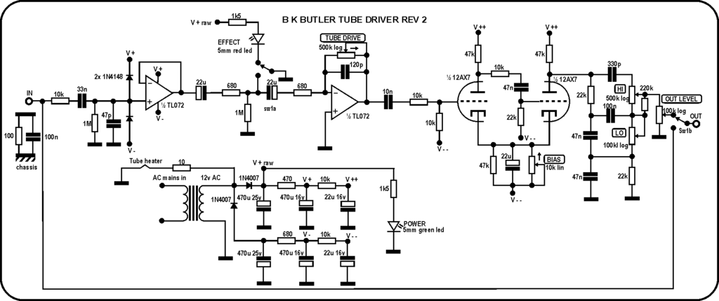
I have seen other (lesser) hacks at the circuit designed to run on 9V supply (such as this) but that doesnt run the tube at proper filament voltage, nor does it supply the 24V rail to rail supply for the tube. My thought was to modify the design for a 12VDC supply. 12VDC filaments, and then use a charge pump to create 24VDC*. Instead of running the tube at +/- 12VDC, i'd run it at 24VDC with the cathodes referenced to ground. A voltage divider is also used to provide a ~12V VR for the op-amp. Schematic like so:

Image

The design works but i'm having low output problems. I know the BK units dont have a whole lot of boost, but this one is pretty much at unity gain when maxed out. I tried adding a second doubler on the charge pump for ~36V and that helped a bit but it was still pretty low output. Is there something i'm missing here? I presumed the +24V rail would be functionally the same as +/- 12V rails, but maybe i'm wrong on that?

*I realize that I could have used the charge pump to generate +/- 12V, but I didnt on this iteration. Humor me.

User avatar
mauman
Resistor Ronker
Information
Posts: 424
Joined: 17 Jun 2017, 20:01
Location: Texas, US
Has thanked: 435 times
Been thanked: 184 times

Post by mauman »

The main thing I notice about your version is no resistance or capacitance between the tube's cathode and ground, while the BK Butler shown, and other versions like the Tube Works RT-901, have R and C in parallel between tube cathode and V-- . Could that be a factor?

User avatar
Manfred
Tube Twister
Information
Posts: 1944
Joined: 04 Apr 2009, 23:42
Has thanked: 1675 times
Been thanked: 1359 times

Post by Manfred »

This is a misconception, you cannot replace this split power supply with a single 24 VDC supply, which results in completely different operating points of the tube stages.
The negative voltage together with the cathode resistor forms a so called pseudo constant current source.
This means that half of the generated constant current is fed into the tube as cathode current and determines the operating point.
The resulting grid cathode voltage is automatically adjusted by the given tube characteristic.
With the single voltage supply shown, the grid voltage is adjusted by the so-called grid leakage current biasing.
This normally requires grid resistors with high values in the megohm range.
Also, this is mostly used in the first stage of an amplifier where the coupling capacitor is not connected to a DC-voltage on the infeed side.
If there is a DC-voltage on, I suppose that the coupling capacitor is charged to the value of the DC-voltage in quiescent mode,
which is then present as a negative grid voltage in respect to the ground.
I have not yet measured this, since I have not yet had the case.
But in the end, the tube stage circuits shown above cannot not work correctly with the single voltage supply.

User avatar
Dr Tony Balls
Diode Debunker
Information
Posts: 843
Joined: 07 May 2009, 14:29
my favorite amplifier: Sunn Model T
Location: Brooklyn, NY
Has thanked: 4 times
Been thanked: 172 times

Post by Dr Tony Balls »

Manfred wrote: 17 Dec 2021, 09:32 This is a misconception, you cannot replace this split power supply with a single 24 VDC supply, which results in completely different operating points of the tube stages.
The negative voltage together with the cathode resistor forms a so called pseudo constant current source.
This means that half of the generated constant current is fed into the tube as cathode current and determines the operating point.
The resulting grid cathode voltage is automatically adjusted by the given tube characteristic.
With the single voltage supply shown, the grid voltage is adjusted by the so-called grid leakage current biasing.
This normally requires grid resistors with high values in the megohm range.
Also, this is mostly used in the first stage of an amplifier where the coupling capacitor is not connected to a DC-voltage on the infeed side.
If there is a DC-voltage on, I suppose that the coupling capacitor is charged to the value of the DC-voltage in quiescent mode,
which is then present as a negative grid voltage in respect to the ground.
I have not yet measured this, since I have not yet had the case.
But in the end, the tube stage circuits shown above cannot not work correctly with the single voltage supply.
Thanks for the information, but unfortunately this didnt seem to do the trick (unless i'm now missing something different). I reconfigured the charge pump to provide +/- 12V and got the same results. Using this schematic now:

Image


mauman wrote: 17 Dec 2021, 03:21 The main thing I notice about your version is no resistance or capacitance between the tube's cathode and ground, while the BK Butler shown, and other versions like the Tube Works RT-901, have R and C in parallel between tube cathode and V-- . Could that be a factor?
The original BK Butler units had the cathodes referenced direct to the negative voltage, which is what i'm doing, and presumed it would work acceptably. My understanding is that the cathode resistor/cap/pot was an optional bias control that could be added to control gain, but it wasnt on most production units. I can try that mod and see what it turns up.

User avatar
plush
Cap Cooler
Information
Posts: 643
Joined: 08 Dec 2015, 09:29
Location: Moscow, Evil Russia
Has thanked: 36 times
Been thanked: 172 times

Post by plush »

Dr Tony Balls wrote: 20 Dec 2021, 15:17
Thanks for the information, but unfortunately this didnt seem to do the trick (unless i'm now missing something different). I reconfigured the charge pump to provide +/- 12V and got the same results. U
It's not about negative voltage reference, but a cathode resistor/cap combo which you've butchered.

This section works with single rail supply and there's no real need for a split one tho.

User avatar
ppluis0
Diode Debunker
Information
Posts: 915
Joined: 14 Jul 2010, 18:33
Location: Argentina
Has thanked: 127 times
Been thanked: 299 times

Post by ppluis0 »

Dr Tony Balls wrote: 16 Dec 2021, 17:12 The design works but i'm having low output problems.
Hi Tony,

Are you tried with another tube ?
Perhaps the tube itself it's failed and does not work properly :roll:
This pedal works with any dual triode with same pin assignment and heater voltage than a 12AX7
So, if you have an 12AT7, 12AU7, ECC83, ECC82, ECC81, 12AY7, 12DW7, etc., you can plug any other tube in the same socket to see what happens.

Cheers,
Jose

User avatar
Manfred
Tube Twister
Information
Posts: 1944
Joined: 04 Apr 2009, 23:42
Has thanked: 1675 times
Been thanked: 1359 times

Post by Manfred »

I wrote
But in the end, the tube stage circuits shown above cannot not work correctly with the single voltage supply.
Sorry, I obviously misguided you with this statement.
I should have better said that the circuit with the single voltage supply without cathode resistor and change of the anode resistance value can not work as desired.
The change to the -12V instead the ground also changes nothing.
As already mentioned, the very low grid leakage current does not result in any significant voltage drop at the 10k grid resistors.
At the cathode and at the base of the grid resistor the voltage is -12V, so at the same potential.
This results in the voltage between grid and cathode being 0V, which is not a working operating point setting.
For example, here is a circuit for a single voltage supply of +30V:
https://www.hgamps.com/low-voltage-tube-preamplifier/
But this circuit delivers only clean sounds.
Personally, I would stay with the tried and tested Tube Driver circuits.

User avatar
Dr Tony Balls
Diode Debunker
Information
Posts: 843
Joined: 07 May 2009, 14:29
my favorite amplifier: Sunn Model T
Location: Brooklyn, NY
Has thanked: 4 times
Been thanked: 172 times

Post by Dr Tony Balls »

plush wrote: 20 Dec 2021, 16:33
Dr Tony Balls wrote: 20 Dec 2021, 15:17
Thanks for the information, but unfortunately this didnt seem to do the trick (unless i'm now missing something different). I reconfigured the charge pump to provide +/- 12V and got the same results. U
It's not about negative voltage reference, but a cathode resistor/cap combo which you've butchered.
This cannot be the case as the original units did not have a cathode resistor/cap. The cathode cap/resistor and bias pot should serve to lower the gain of the triodes, and at its lowest setting the cathode cap/resistor are bypassed. I've proven this by test, adding the cathode resistor/cap/bias pot and the results are the same.

Also, FWIW, telling someone they've "butchered" something on a forum designed for education doesnt come across as very productive.


ppluis0 wrote: 20 Dec 2021, 18:11
Dr Tony Balls wrote: 16 Dec 2021, 17:12 The design works but i'm having low output problems.
Hi Tony,

Are you tried with another tube ?
Yeah, plenty. In fact it seems very tube dependant with some 12AX7s performing better than others. Even the best is still low though.


Manfred wrote: 23 Dec 2021, 01:05 I wrote
But in the end, the tube stage circuits shown above cannot not work correctly with the single voltage supply.
Sorry, I obviously misguided you with this statement.
I should have better said that the circuit with the single voltage supply without cathode resistor and change of the anode resistance value can not work as desired.
The change to the -12V instead the ground also changes nothing.
As already mentioned, the very low grid leakage current does not result in any significant voltage drop at the 10k grid resistors.
At the cathode and at the base of the grid resistor the voltage is -12V, so at the same potential.
This results in the voltage between grid and cathode being 0V, which is not a working operating point setting.
For example, here is a circuit for a single voltage supply of +30V:
https://www.hgamps.com/low-voltage-tube-preamplifier/
But this circuit delivers only clean sounds.
Personally, I would stay with the tried and tested Tube Driver circuits.
Thanks. At this point about the only difference between mine and the tried and tested circuits is my power supply, which leads me to believe that it's not providing ample current. Looking at the MAX1044 datasheet (presuming i'm reading it correctly) it seems to have a max supply current of 200μA. I'm having a hard time pinning down the precise current demands of a 12AX7 at ~24V but it seems that it would greatly exceed 200μA.

User avatar
mauman
Resistor Ronker
Information
Posts: 424
Joined: 17 Jun 2017, 20:01
Location: Texas, US
Has thanked: 435 times
Been thanked: 184 times

Post by mauman »

The MAX1044/ICL7660 are spec'ed at 10 mA: "They deliver 10mA with a 0.5V output drop..." the 200 uA is the quiescent no-load supply current. You can pull more than 10 mA from it, but the output voltage continues to drop and you get more heat generated (max rating is 727 mW.) But you may indeed need more current. The Intersil 7660S is good to 45 mA, and the TI LT1054CP is rated to 100 mA (although it has a different pinout.)

User avatar
Manfred
Tube Twister
Information
Posts: 1944
Joined: 04 Apr 2009, 23:42
Has thanked: 1675 times
Been thanked: 1359 times

Post by Manfred »

. Looking at the MAX1044 datasheet (presuming i'm reading it correctly) it seems to have a max supply current of 200μA.
I'm having a hard time pinning down the precise current demands of a 12AX7 at ~24V but it seems that it would greatly exceed 200μA.
Have a look at this post:
viewtopic.php?t=28759
For a friend of mine I converted this pedal to 9VDC.
Since the internal operating voltage is generated by a 12V voltage regulator, I needed a higher input voltage at its input.
Since the MAX1044 as well as the 7606 cannot supply enough current I used this voltage converter with the TDA2003.
At the beginning it did not work because of audible noise. I then added a current compensated choke,
as well as like an electrolytic capacitor with a value of 470uF to the output of the voltage regulator in the manner shown, the noises were then gone.
This is only for a single power supply.
Last edited by Manfred on 28 Dec 2021, 23:30, edited 1 time in total.

User avatar
Manfred
Tube Twister
Information
Posts: 1944
Joined: 04 Apr 2009, 23:42
Has thanked: 1675 times
Been thanked: 1359 times

Post by Manfred »

Here the Shaka tube circuit with separate cathode circuit for each stage:
shaka_tube_revised_1_6_03.gif
shaka_tube_revised_1_6_03.gif (7.73 KiB) Viewed 1428 times

User avatar
ppluis0
Diode Debunker
Information
Posts: 915
Joined: 14 Jul 2010, 18:33
Location: Argentina
Has thanked: 127 times
Been thanked: 299 times

Post by ppluis0 »

Hi Manfred,

Please take a look at this link: https://www.hagamps.com/collections/ped ... oost-pedal

The schematic diagram appears at last page of user manual and reveals similar topology than Shaka tube, but running only at 9 Vdc

Cheers,
Jose

User avatar
Manfred
Tube Twister
Information
Posts: 1944
Joined: 04 Apr 2009, 23:42
Has thanked: 1675 times
Been thanked: 1359 times

Post by Manfred »

The value of the bias pot is 10 Kiloohms.
Shaka Tube sound demo:
shakaTubeDemo.mp3
(2.16 MiB) Downloaded 51 times

Post Reply