The sleep plays tricks
Dunlop - Octavio
Alex Frias wrote:I figured out something like this:
But I imagine the pot value is something higher than the 1K we are used to...

I do not understand the meaning......
in any case the pot gain and the cap 22UF is not connected to the resistances 1K/47K...
-
Alex Frias

- Resistor Ronker
Why not?
I just follow the info our friend RnFR gave us about the gain pot wiring and the pics Alnico provided.
It's very close to the Tycho, but with small changes. The gain control is one, I believe.
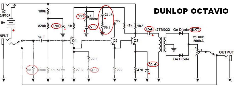
There is one more electrolitic (22uF in this Dunlop box) capacitor than in Tycho schematics. And at one of its lids is conected to the 5K1 resistor, which goes to ground, and the other lid goes to the the knot conecting the resistors (1K and 47K) and one terminal of the gain pot. I assume, by the clues, that the other gain pot terminal goes to the other 22uF, on the right of the trafo, wich goes to ground too at it's other end. So my only doubt is about the value of the gain pot, and it's not bad to check the level pot too, just to have it all done.
Now we can face those two RC "arms" as the "gain control engine". Maybe a way they found to get a more responsive gain control.
I may try out puting a 10K log, just to see what happens...
I just follow the info our friend RnFR gave us about the gain pot wiring and the pics Alnico provided.
It's very close to the Tycho, but with small changes. The gain control is one, I believe.
There is one more electrolitic (22uF in this Dunlop box) capacitor than in Tycho schematics. And at one of its lids is conected to the 5K1 resistor, which goes to ground, and the other lid goes to the the knot conecting the resistors (1K and 47K) and one terminal of the gain pot. I assume, by the clues, that the other gain pot terminal goes to the other 22uF, on the right of the trafo, wich goes to ground too at it's other end. So my only doubt is about the value of the gain pot, and it's not bad to check the level pot too, just to have it all done.
Now we can face those two RC "arms" as the "gain control engine". Maybe a way they found to get a more responsive gain control.
I may try out puting a 10K log, just to see what happens...
One moment ...
The potentiometer is connected through capacitor and not the reverse.
Gain potentiometer should go to ground.
The resistor is 5.1K instead of the pot .... but not connected in normal mode
Am i wrong?
I would like to see the wiring with pot ...
The potentiometer is connected through capacitor and not the reverse.
Gain potentiometer should go to ground.
The resistor is 5.1K instead of the pot .... but not connected in normal mode
Am i wrong?
I would like to see the wiring with pot ...
-
Alex Frias
- Resistor Ronker
I'm assuming the orange and the light grey cables are from the gain pot terminals... or boost as it is also called.
The pot with the cap AND the resistor with another cap are there! I think just to work together for better gain control performance, I believe.
Now I ask: Am I wrong? Please, correct me, if you see it differently!
My guessing for now is something like this (Sorry Mr Peña, but I use your Tycho schem for assumed lazyness...):
-
Alex Frias
- Resistor Ronker
I tested the "gain/boost control engine" using a 10K pot and it works very well, with a very large range of drive setings.
-
RnFR

- Old Solderhand
Information
just to be precise regarding the schematic- remember that there is no AC adapter, and that there is an on/off switch on the volume pot. but i think this is just a preliminary version anyway, right?  i'll try and get those pot values later today if i get time. if not, it'll get done wednesday.
"You've converted me to Cubic thinking. Where do I sign up for the newsletter? I need to learn more about how I can break free from ONEism Death Math." - Soulsonic
Blog-APOCALYPSE AUDIO
Blog-APOCALYPSE AUDIO
-
Alex Frias
- Resistor Ronker
Exactly, it's just to understand it a bit more...
Argh!!Alex Frias wrote:I'm assuming the orange and the light grey cables are from the gain pot terminals... or boost as it is also called.
The pot with the cap AND the resistor with another cap are there! I think just to work together for better gain control performance, I believe.
maybe you're right..
you've tried it and it sounds good?
-
Alex Frias
- Resistor Ronker
Yeah, now the gain/boost control operates on a very reasonable way, way cool I must say!
Soon I will try to post a sound clip or a utoobe vid, but I would like to confirm all the values and possibly replace the 1N34a with 1N270, just to get it closer to the beast. But it seems to be very close to the Dunlop box than before.
In relation to the 1n270: I don't know what happened with the itens bought from SmallBear, maybe two monthes is too much time to get it delivered, but maybe Christmas was a very busy time for the post services... The order I made before that one was so quickly delivered...
-
sinner
- Old Solderhand
Information
- Posts: 4709
- Joined: 06 Nov 2008, 17:16
- Location: ...no more
- Has thanked: 1031 times
- Been thanked: 909 times
Maybe your custom office got itAlex Frias wrote:In relation to the 1n270: I don't know what happened with the itens bought from SmallBear, maybe two monthes is too much time to get it delivered, but maybe Christmas was a very busy time for the post services... The order I made before that one was so quickly delivered...
-
Alex Frias
- Resistor Ronker
It's way below the importing limits. But even when it happens we received a note from the customs office containing taxes and how to proceed. but I will try to contact Steven again, as I know he is a very responsible guy. I'm just sad for the delay, but I'm not blaming SmallBear anyway, just doubting if the ordered itens will reach me... You know, with no tracking facility a lot of things may happen. Well, it's not the end of the world. 
-
azrael

- Cap Cooler
Does anyone know if Q1 is oriented correctly or not in this version? I just built one with it oriented "correctly".
EDIT: nevermind I just saw the schematic haha. I'll be match my GGG build to their component values....
EDIT: nevermind I just saw the schematic haha. I'll be match my GGG build to their component values....
-
Alex Frias
- Resistor Ronker
I'm not sure if I understood what you mean, but...
The circuit I posted is just to show up the differences about component values and added ones between the Tonepad Octavia and the Dunlop Octavio. The Dunlop box has a positive ground orientation, so the trannies position is obviously reversed. Sorry if it caused some confusion...
The circuit I posted is just to show up the differences about component values and added ones between the Tonepad Octavia and the Dunlop Octavio. The Dunlop box has a positive ground orientation, so the trannies position is obviously reversed. Sorry if it caused some confusion...
-
Alex Frias
- Resistor Ronker
theoretically I tend to say:"no way, they sound the same!"
But I must try to do it both ways to clear any doubt... empyrically, if there's such a word in english idiom.
For now I have a one positive ground, with those modified values and this nes "gain/boost engine", but with 1N34A diodes in place of 1N270 (as I said, my order from SmallBear didn't make it for now) and a 10K gain/boost pot as I don't know the value used by Dunlop. Anyway it sounds really good and very close to the clips we see and listen, obviously you may consider the equipment and player differences.
-
Alex Frias
- Resistor Ronker
The order from SmallBear arrived 
So I disoldered the 1N34A and replace them with the 1N270. I think, except for the boost/gain pot, it's the best I could do to get close to the Dunlop box. I really can't say if the diodes exchange changed the final sound, but certainly didn't make a strong difference. Anyway I recorded a one more crappy sound clip. Hope it serves as an overall idea.
It was recorded direct to the computer by a clean amp modeler emulation. Neck pickup on my Parker P-30, with Gold Lace Sensor. First half with the gain/boost on the 12 oçlock, the other half full on blast.
 octaviodun1.rar
- (820.01 KiB) Downloaded 326 times
-
John Lyons

- Solder Soldier
Sound great! Nice job.
-
Alex Frias
- Resistor Ronker
Thanks, John, now i have to find a little time to spend on the negative ground version using the cool PCB created by our friend here.