I just got done building the GT2, using a PCB from Small Bear (which is a great PCB), and the PCB is based off of Tonepads layout (http://www.tonepad.com/getFile.asp?id=112).
I added a 3PDT switch to add in the mid band EQ, as posted by Mozwell in this post.
I inserted the switch between IC4b pin (7) outout and the 1K resistor (going into Q1 base).
The switch also switches the 330pf (C8 in the mid band EQ schematic), so I can keep the GT2 tone control normal when I switch off the mid band EQ.
When I first tried this, with the switch in the normal mode, the pedal sounded bad. When I switched in the mid band EQ, the pedal sounded really good, and some of the squealing with the gain turned to max went away. But why did it sound bad in the normal position.
So I connected the last switch of the 3PDT to switch on the power to the mid band EQ.
Now in both the normal, and adding the mid band EQ the pedal sounds really good.
Some questions:
When I switch the 3PDT switch to either position, I get a pop. It did not do this pop until after I connected the power to be switched? Should I put a cap across the switch terminals to get rid of pop?
In normal mode, with controls maxed it is very noisy (which reading on line is happening a lot to this DIY pedal). I am going to try to wrap shielding around some of the wiring, but my question is do you connect one end to ground? Is there a article about properly shielding wiring?
Thanks
Rob
Sansamp gt2 mod
-
caspercody

- Resistor Ronker
-
thesmokingman
- Breadboard Brother
due to the high gain and large amount of off-board wiring, it is going to be noisy and probably more so than a real one which are known to have the same issue. when I built the last one I did, I used higher quality op amps and rotary switches. the only wiring I was really able to shield effectively were the in/out wires and I kept my leads to the switches as short as possible and about all that did was keep it from oscillating at its highest gain settings. there was still a ton of noise.
Not exactly a mod. I made tonepad's GT-2 and I don't want to wire all those switches, so I made a board:
Is there any way I can resize the pictures?


Is there any way I can resize the pictures?
Information
- Posts: 1
- Joined: 22 May 2019, 20:16
mozwell wrote:Found this mid band eq for GT2 on my travels. Hope this helps.
mecmast wrote:Hi, i am new to schematics. May be this is stupid question but is there an IC or Opamp used in this schem? I couldnt figure out the triangles shown with "X4" and "X5". What are they?
Thank you.
Heya, guys.. I would like to bump this thread slightly because I am in need of some clarification, regarding the same issue mecmast already mentioned..
If I understand correctly, the X4 is the is the B side (IC4b if you will) of the op amp. What's the X5? Is it another op amp that needs to be added for the
mid band, and if so, shouldn't there be another 4-pin part? Is it a different IC with just 4 pins?
Any help would be greatly appreciated.
-
andregarcia57
- Cap Cooler
Hey guys!
I want to mod an GT2
1) Make California sound more clean as a boogie channel 1
Decrease the gain a lot to work as a clean fender channel, without any drive, but with EQs and boogie table frequencies
I want to mod an GT2
1) Make California sound more clean as a boogie channel 1
Decrease the gain a lot to work as a clean fender channel, without any drive, but with EQs and boogie table frequencies
-
FiveseveN

- Cap Cooler
Information
Yes, each triangle is one op amp unit, and we usually use dual op amps in one package, like the TL072. There are also quad packages like TL074. This layout uses three dual op amps and it's usually what you'll find for a DIY GT-2:

Regarding the proposed modified tone control, that one requires an extra op amp and adding it is up to you. If it's a "mod" to an assembled board you'd probably bypass the original tone section and add a daughter board with a dual op amp and the passives.
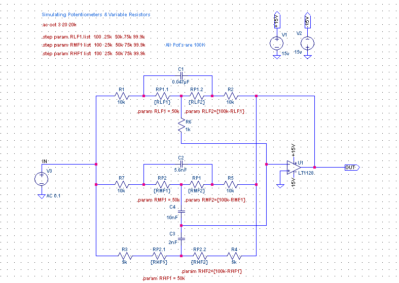
Alternatively you could go with this kind of combined 3-band Baxandall and keep the total op amp count at 6 but I doubt it would be viable to implement as a mod, you're better off rebuilding the tone stack to your needs, or the whole circuit for that matter.
Later edit: I wanted to read the latest post but ended up replying to the last one on the previous page some 7 years late
So about less gain on the Tweed channel without affecting the others: unfortunately IC1b (in reference to the Sin Amp schematic above) is already at unity gain plus there's some attenuation afterwards in the pre-shaping filter. One option is to add a divider including the 100K resistor in that filter, say a 100K trim to Vb. Or just turn the gain down when you switch to that mode. Make sure switch 2 (MOD) is set to Clean. If the minimum gain setting is still distorting, lower the 3.3K attached to the gain pot, down to zero if needed.
Regarding the proposed modified tone control, that one requires an extra op amp and adding it is up to you. If it's a "mod" to an assembled board you'd probably bypass the original tone section and add a daughter board with a dual op amp and the passives.
Alternatively you could go with this kind of combined 3-band Baxandall and keep the total op amp count at 6 but I doubt it would be viable to implement as a mod, you're better off rebuilding the tone stack to your needs, or the whole circuit for that matter.
Later edit: I wanted to read the latest post but ended up replying to the last one on the previous page some 7 years late
So about less gain on the Tweed channel without affecting the others: unfortunately IC1b (in reference to the Sin Amp schematic above) is already at unity gain plus there's some attenuation afterwards in the pre-shaping filter. One option is to add a divider including the 100K resistor in that filter, say a 100K trim to Vb. Or just turn the gain down when you switch to that mode. Make sure switch 2 (MOD) is set to Clean. If the minimum gain setting is still distorting, lower the 3.3K attached to the gain pot, down to zero if needed.
Ignorance more frequently begets confidence than does knowledge. (Charles Darwin)